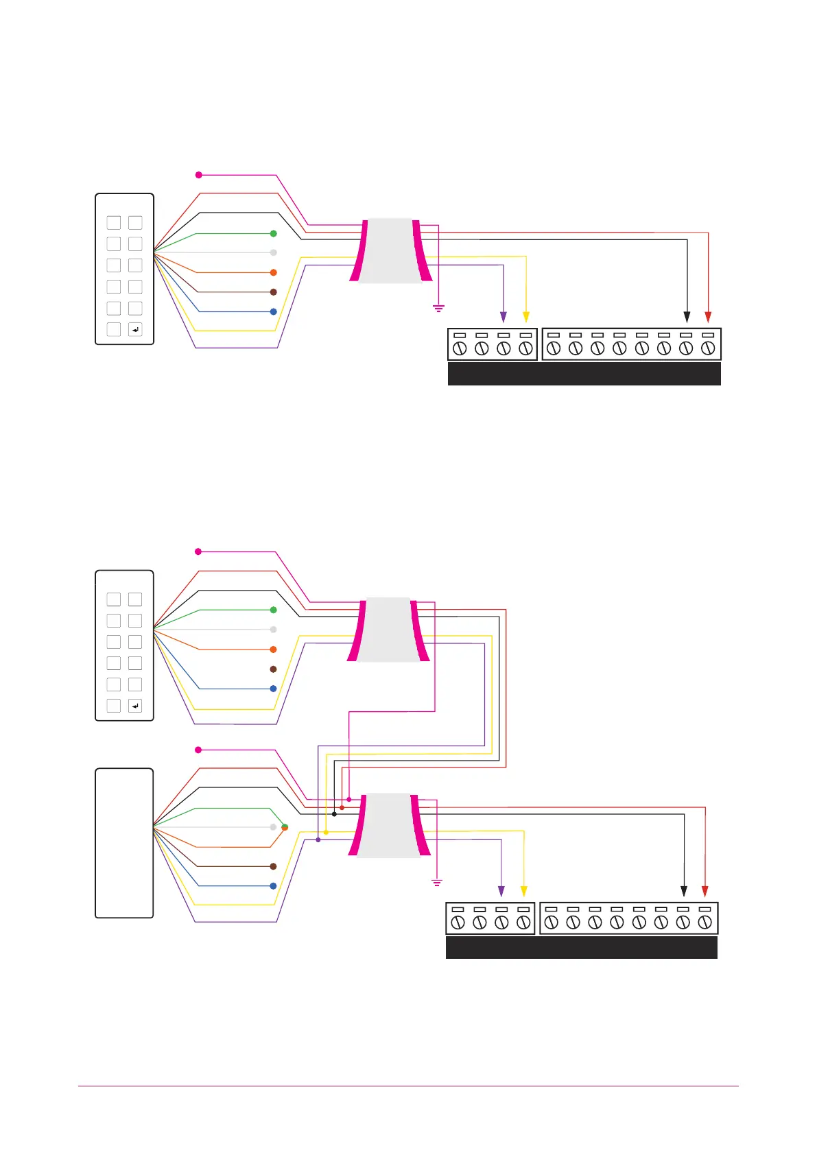
RS-485 Reader Connection (Entry Only)
The following diagram shows the connection of a single RS-485 reader connected in entry only mode.
V+
V-Z4 V- Z3 Z2 V- Z1BZ L1
D1/
NB
D0/
NA
Shield is frame
grounded at
one point
1 2
3 4
5 6
7 8
9 0
X
RED
BLACK
SHIELD
GREEN
WHITE
ORANGE
BROWN
BLUE
YELLOW
VIOLET
Reader shield is
not terminated
inside the reader
Shield wires
connected
at the splice
When the green and orange wires are not connected together, the reader defaults to an entry reader.
RS-485 Reader Connection (Entry/Exit)
The following diagram shows the connection of two RS-485 readers connected to provide an entry/exit
configuration.
V+
V-Z4 V- Z3 Z2 V- Z1BZ L1
D1/
NB
D0/
NA
Shield is frame
grounded at
one point
ENTRY
EXIT
1 2
3 4
5 6
7 8
9 0
X
RED
BLACK
SHIELD
GREEN
WHITE
ORANGE
BROWN
BLUE
YELLOW
VIOLET
Reader shield is
not terminated
inside the reader
Shield wires
connected
at the splice
RED
BLACK
SHIELD
GREEN
WHITE
ORANGE
BROWN
BLUE
YELLOW
VIOLET
Shielded Cable
Shielded Cable
The exit reader has the green and orange wires connected together.
A 330 ohm EOL (End of Line) resistor may be required to be inserted between the NA and NB terminals of the
reader port.
PRT-CTRL-DIN | Protege GX DIN Rail Integrated System Controller | Installation Manual 20