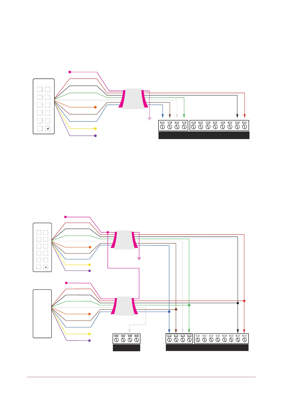
Wiegand Reader Connection
The controller allows the connection of 2 magnetic clock and data reading devices or 4 Wiegand reading devices
and the ability to control 2 doors (entry or exit only) or 1 door (entry and exit). The following diagrams show the
connection of a standard Wiegand reader with the controller controlling an access door and an entry/exit door.
VIOLET
YELLOW
BLUE
BROWN
ORANGE
WHITE
GREEN
BLACK
RED
SHIELD
Shielded Cable
Shield is frame
grounded at
one point
Reader shield is
not terminated
inside the reader
Shield wires
connected
at the splice
V+
V-Z4 V- Z3 Z2 V- Z1BZ L1
D1/
NB
D0/
NA
1 2
3 4
5 6
7 8
9 0
X
Multiple Wiegand Reader Connection
Multiple reader mode allows the connection of 4 Wiegand reading devices controlling 2 doors each with entry/exit
readers.
In multiple reader mode, the secondary reader has all connections wired to the same port as the primary card
reader, with the DATA 1 connection wired to the opposite reader connection DATA 1 input.
The reader that is multiplexed into the alternate reader port will operate as the exit reader, and the normal reader
connection operates as the entry reader.
V+
V-Z4 V- Z3 Z2 V- Z1BZ L1
D1/
NB
D0/
NA
BZ L1
D1/
NB
D0/
NA
ENTRY
EXIT
1 2
3 4
5 6
7 8
9 0
X
VIOLET
YELLOW
BLUE
BROWN
ORANGE
WHITE
GREEN
BLACK
RED
SHIELD
VIOLET
YELLOW
BLUE
BROWN
ORANGE
WHITE
GREEN
BLACK
RED
SHIELD
Shield is frame
grounded at
one point
Shielded Cable
Shielded Cable
Reader shield is
not terminated
inside the reader
Shield wires
connected
at the splice
PRT-CTRL-DIN | Protege GX DIN Rail Integrated System Controller | Installation Manual 21