Inputs
The controller has 8 onboard inputs for monitoring the state of devices such as magnetic contacts, motion
detectors and temperature sensors. Devices connected to the inputs can be installed to a maximum distance of
300m (1000ft) from the module when using 22 AWG wire.
⦁ Magnetic contacts shall be listed to UL 634 to comply with UL installation standards and
ULC/ORD-C634 to comply with ULC installation standards.
⦁ Motion detectors and temperature sensors shall be listed to UL 639 to comply with UL
installation standards and ULC-S306 to comply with ULC installation standards.
⦁ The controller has been evaluated for UL 294, UL 1076, UL 1610, UL 1635, CAN/ULC-S304,
CAN/ULC-S319 and CAN/ULC-S559.
Inputs can be programmed using the Protege software. Inputs CP001:01 to CP001:08 represent the controller's
onboard inputs. Additional inputs are supported through the use of expansion modules.
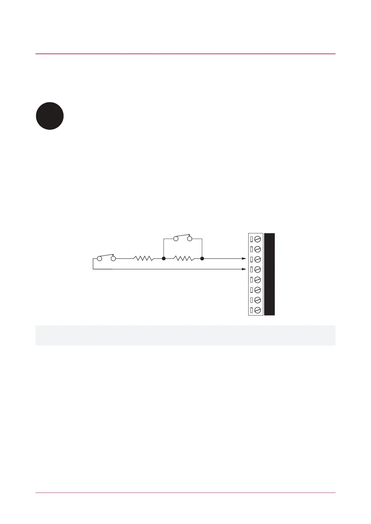
The controller supports normally opened and normally closed configurations with or without EOL resistors. When
using an input with the EOL resistor configuration, the controller generates an alarm condition when the state of
an input changes between open and closed and generates a tamper alarm condition when a wire fault (short
circuit) or a cut wire (tampered) in the line occurs. Inputs default to require the EOL resistor configuration.
EOL Resistor Input Configuration
N.C Input Contact
N.C Tamper 1K 1K
V+
V-Z4 V- Z3 Z2 V- Z1
Inputs 1-4 and 5-8 can operate as either general purpose inputs or as onboard reader inputs. If used as general
purpose inputs you must ensure that they are not defined in the onboard reader set up.
Each input can use a different input configuration. To program a large number of inputs with the same
configuration use the multiple selection feature within the Protege software.
When using the 'No Resistor' configuration the controller only monitors the opened and closed state of the
connected input device, generating the alarm (open) and restore (closed/sealed) conditions.
PRT-CTRL-DIN | Protege GX DIN Rail Integrated System Controller | Installation Manual 26