T
TELECOM
EQUIPMENT
24h Standby / Backup
Required for Telecom
Equipment
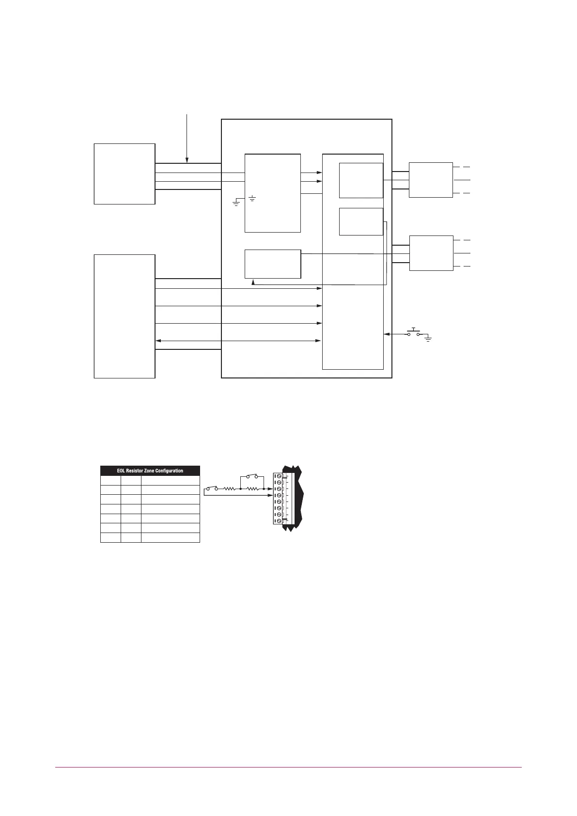
Note: All cables shall be protected within metal conduits.
* EOL resistor must be installed at the Fire Alarm Control Panel Output.
Typical Zone Circuits
Value 1 Value 2 Monitored Status
1K 1K Open, Close, Tamper, Short
6K8 2K2 Open, Close, Tamper, Short
10K 10K Open, Close, Tamper, Short
2K2 2K2 Open, Close, Tamper, Short
4K7 2K2 Open, Close, Tamper, Short
4K7 4K7 Open, Close, Tamper, Short
+AUX- Z1 COM COMZ2 Z3 Z4
N.C
Tamper
N.C Zone Contact
Value 2 Value 1
+
-
+
-
ULC certified 12V DC Power Supply
12V DC
485 485
+ -
C NC NCC
12VDC
AC
FAIL
BATT
FAIL
* The AC FAIL output on the Power Supply MUSTbe programmed to follow the AC Trouble Input as follows:
AC FAIL = OPEN on fail
USB
ANTENNA
CELLULAR MODEM
N.O Zone Contact
RESET Push Button
Z4
* Fire zones shall be separated from burglar zones through area partitioning.
* Fire zones Z1-Z3 shall be used exclusively for fire monitoring and cannot be programmed to activate the bell output
* Fire Zone Z4 N.O Push Button to be used as monitoring reset switch.
Programmable
Output
N+ N-