Figure 5-1 shows all the possible rear panel connectors for the DM series LCD monitor.
Refer to Table 5-1 for a list of the monitors and their corresponding connectors. The
following sections fully describe the rear panel connectors for the DM series LCD monitor.
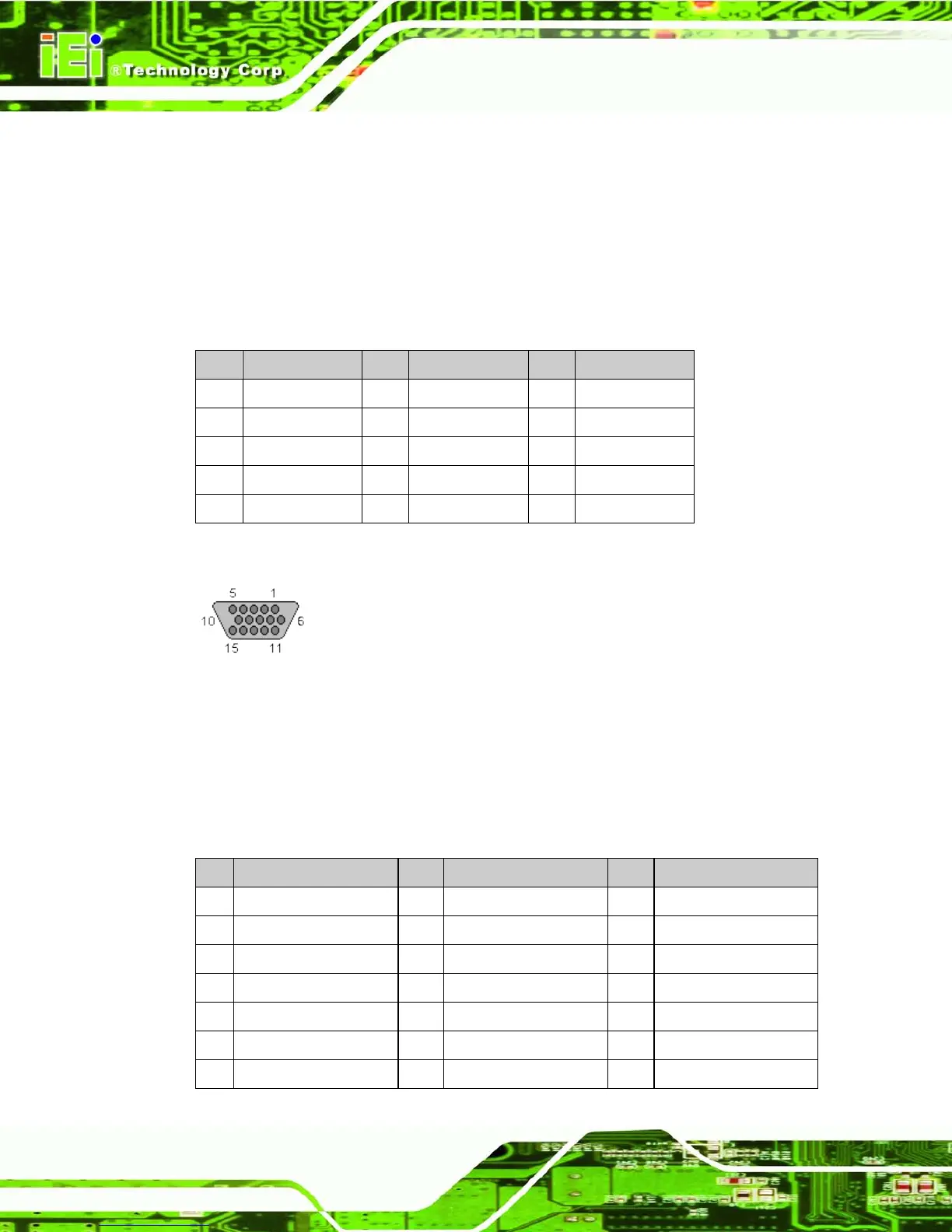
5.4.2 VGA Connector
Use the rear panel standard 15-pin female VGA connector to connect the monitor to the
system graphics interface.
PIN DESCRIPTION PIN DESCRIPTION PIN DESCRIPTION
1 RED 6 GROUND 11 NC
2 GREEN 7 GROUND 12 DDCDAT
3 BLUE 8 GROUND 13 HSYNC
4 NC 9 NC 14 VSYNC
5 GROUND 10 GROUND 15 DDCCLK
Table 5-2: VGA Connector Pinouts
Figure 5-2: VGA Connector
5.4.3 DVI-D Connector
Use the rear panel standard 24-pin female DVI-D connector to connect the monitor to the
system graphics interface.
PIN DESCRIPTION PIN DESCRIPTION PIN DESCRIPTION
1 TMDS Data2- 9 TMDS Data1- 17 TMDS Data0-
2 TMDS Data2+ 10 TMDS Data1+ 18 TMDSData0+
3 TMDS Data2/4 Shield 11 TMDS Data1/3 Shield 19 TMDS Data0/5 Shield
4 TMDS Data4- 12 TMDS Data3- 20 TMDS Data5-
5 TMDS Data4+ 13 TMDS Data3+ 21 TMDS Data5+
6 DDC Clock [SCL] 14 +5 V Power 22 TMDS Clock Shield
7 DDC Data [SDA] 15 Ground (for +5 V) 23 TMDS Clock +
 Loading...