P13
Step 1: iCANnet control wiring
Objective: To identify the layout of the CAN network (also known as iCANnet) and connect the SCRP Switched Relay
Controller (and other devices) to it. Verify the electrical characteristics of the network and terminate the end devices.
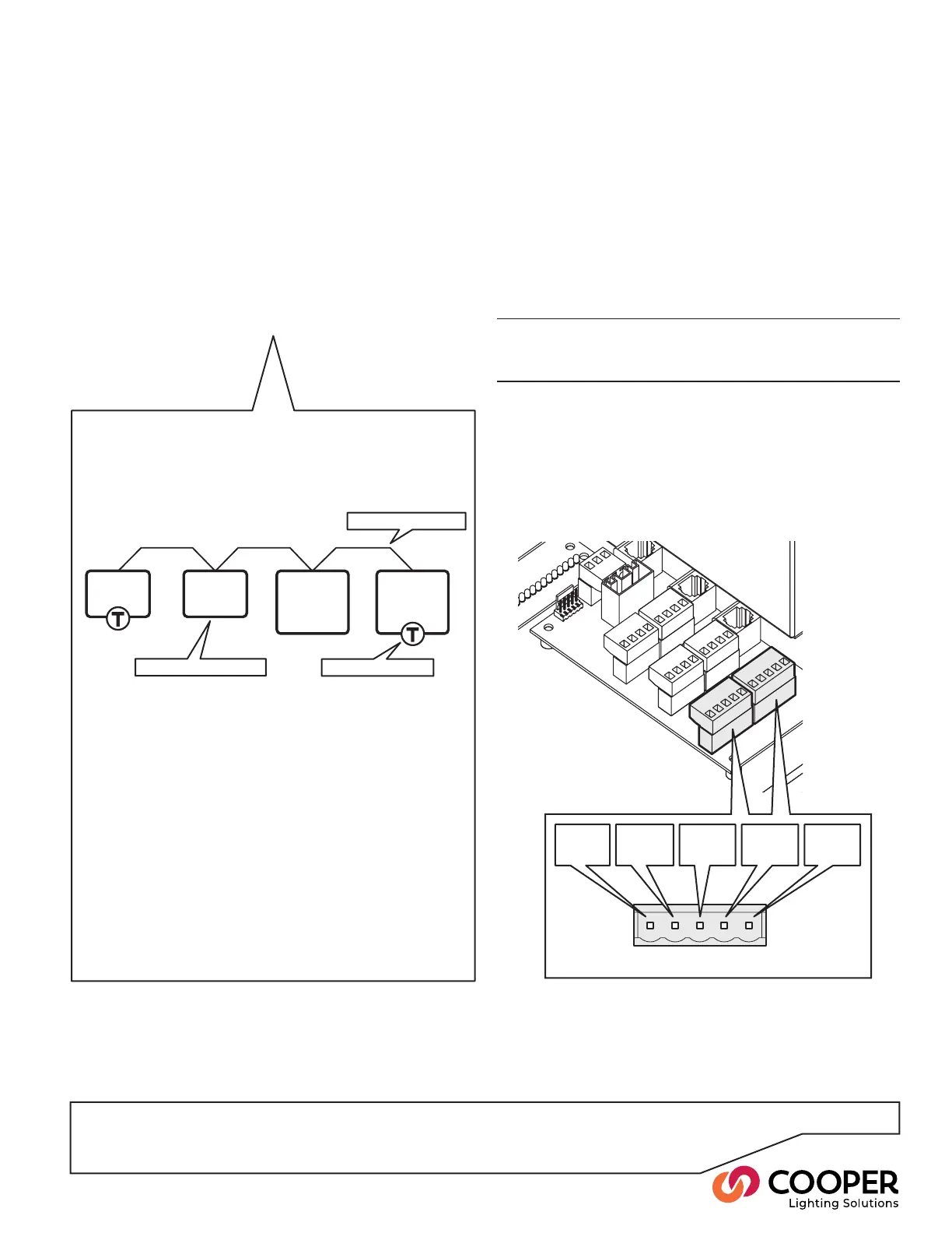
+12V
(red)
CAN-H
(white)
DRAIN
(gray)
0V
(black)
CAN-L
(blue)
To wire all devices to the CAN network
1. Open the main panel door.
2. If not already done, feed the CAN network cable(s)
from the top of the panel to the control board area.
Note: There should be two CAN network cables un-
less the SCRP Switched Relay Controller is at the end
of the network segment, in which case there will only
be one cable.
IMPORTANT: Keep all low voltage control wiring sepa-
rate from high voltage power cabling to ensure safety
and noise immunity.
4. Connect the CAN network cable(s) to the iCAN
connector(s) on the control board according to the
following pin-outs:
5. Connect all other remaining devices to the CAN
network according to the installation plans and the
specic instructions for each device.
SC-UN
source
controller
SC-UN
source
controller
Wall-
station
Wall-
station
CAN network wiring
Un-terminated device
Terminated device
General CAN network requirements
The CAN network requires devices to be linked to-
gether in a daisy-chain arrangement. A single run of
daisy-chained devices is called a Segment.
There are three main constraints for a CAN network
segment:
• The combined cable lengths of the segment may
not exceed 3280 feet (1000 meters), and
• No more than 100 devices or nodes may be con-
nected within a single segment.
• Terminate the devices at each end of the segment
with a 120- ohm resistor. Leave the remaining
devices on the segment un-terminated.
Where more than 100 devices or excessive overall
cable lengths are required, it is necessary to use a
Bridge device to link two or more segments together.
Contact Cooper Lighting Solutions for details about
bridge devices.
To identify the CAN network wiring layout
1. Use the installation plans to determine the layout of
the installed CAN network.
2. Determine where the SCRP Switched Relay
Controller(s) are connected in the CAN network. In
particular, identify the devices that are located at either
end of the CAN network segment - these are the de-
vices that must be terminated.