P16
Supply Wiring
Wiring ow
The SCRP Switched Relay Controller range has been de-
signed to provide a clear layout and logical progression for all
power circuits.
The circuit hot conductors enter at the top panel and connects
directly to the “Line” terminal on the relay card lugs.
Two vertical wireways provide clear routes from the circuit
card outputs up to the exiting top of the chassis.
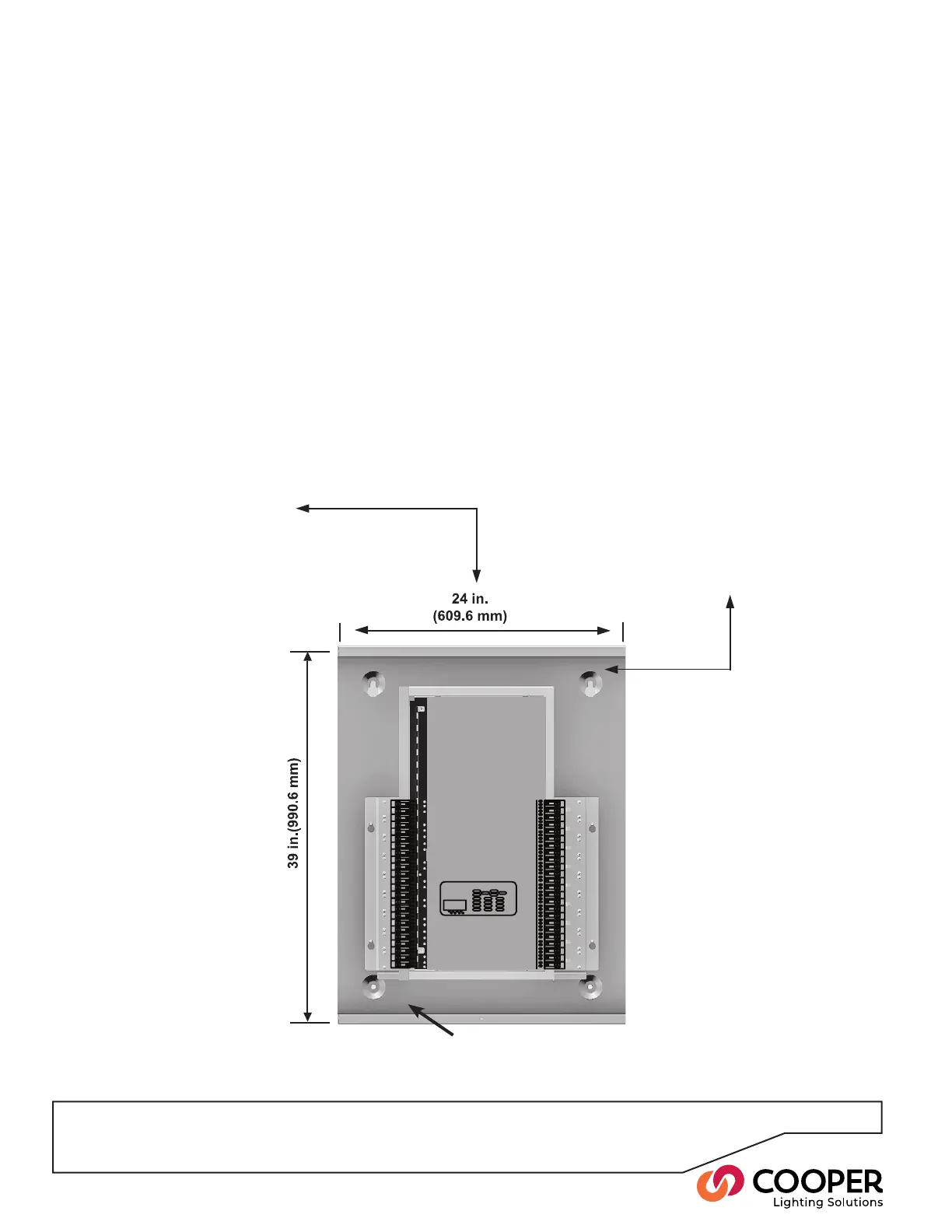
The diagram shown below indicates a typical wiring ow with
the high voltage load wiring from the various channels (and
their earth connections) exiting from the top panel wiring
diagram.
Relay connections to
lighting loads (conduit
may enter through side or
side top of the enclosure).
Low-voltage connections for
ICANnet, DMX512, RS485,
Ethernet, Contact Closures,
0-10V Dimming come into the
center top section of the
enclosure.
Left High
Voltage Channel
Low Voltage Only
Right High
Voltage Channel
Source Power
Ground
Optional Barriers are available to sep-
erate voltages or sources.
Step 3: Power up the Switched Relay Controller