P26
Step 10: Connect and Congure Contact Inputs
To congure contact inputs
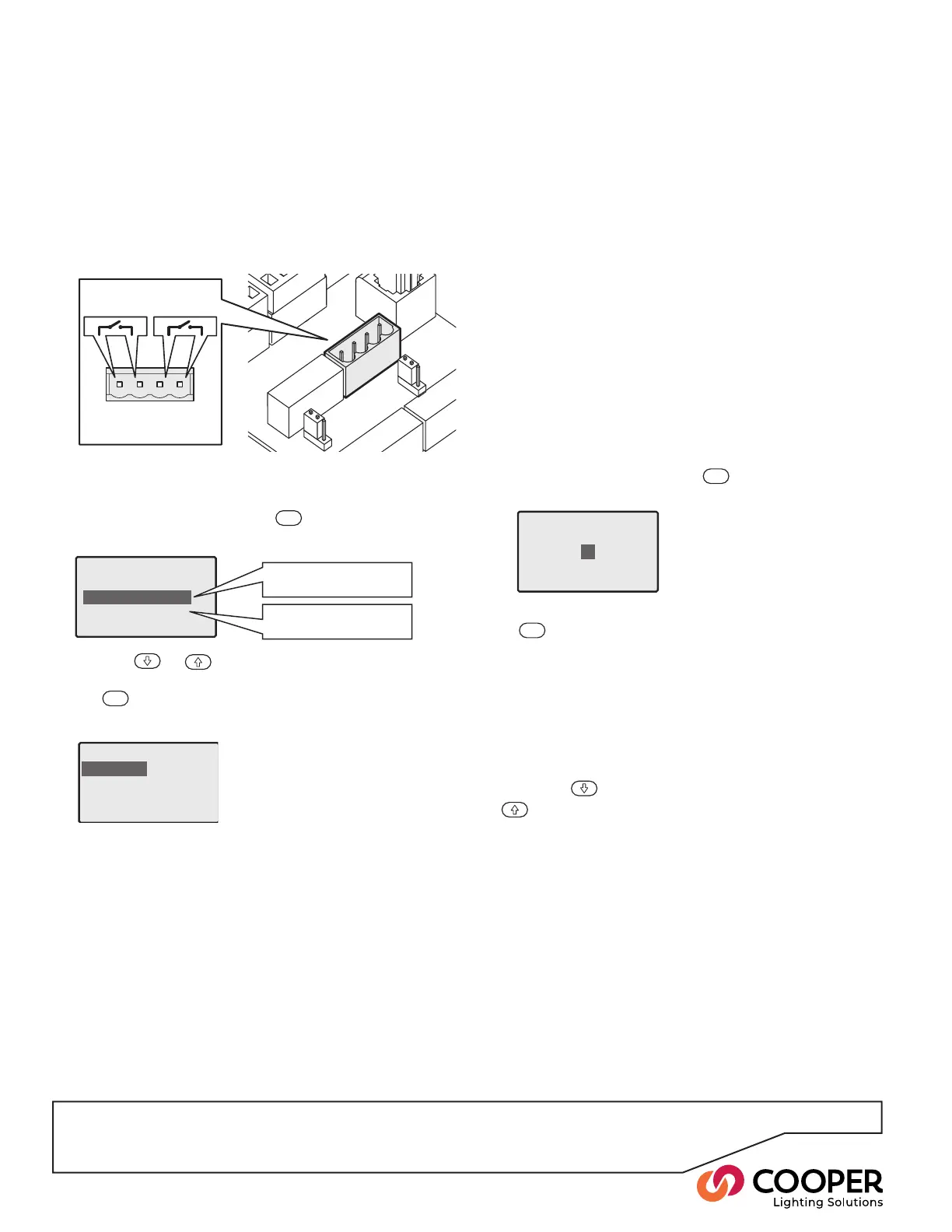
1. From the Conguration menu, highlight the ‘Contact
Inputs’ option and press the
ENT
button. The display
will show the current settings for the rst input:
Contact Inputs
Input 1
Open:DoNothing
Close: Do Nothing
Action activated when
the contact input opens
Action activated when
the contact input closes
Input 1: Open
Do Nothing
Enter Emergency State
Exit Emergency State
Select Scene 1
Contact Inputs
Select Scene
1
• Do Nothing The SCRP Switched Relay Controller
will ignore the input state.
• Enter Emergency State When the contact input
condition becomes true, the SCRP Switched Relay
Controller will enter the special Emergency State.
While in this state, the levels congured for the
Emergency Scene will be used and the unit will not
respond to most iCAN messages until the Emer-
gency State is cancelled. The Emergency State can
be cancelled either upon receipt of a special iCAN
message or by using the ‘Exit Emergency State’ on
the opposing contact input condition.
• Exit Emergency State When the contact input con-
dition becomes true, the Emergency State will be
cancelled, all iCAN messages will be accepted and
normal operation will resume with the scene last
displayed before the Emergency State.
• Select Scene xxx When the contact input condition
becomes true, the outputs of the SCRP Switched
Relay Controller will change to those dened within
the selected scene number. When this setting is
chosen and you press the
ENT
button, a second
screen will prompt you to enter a scene number:
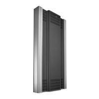
Contact
Switch
input 1
Switch
input 2
Enter the appropriate scene number and press the
ENT
button.
3. Repeat step 2. for the alternate condition within the
same contact input. For instance, if the ‘Close’ contact
input condition is set to ‘Enter Emergency State’, then
the corresponding ‘Open’ condition should be set to
‘Exit Emergency State’ in order to return the SCRP
Switched Relay Controller back to normal operation.
4. If necessary, congure the other contact input by using
either the
button to scroll down to ‘Input 2’ or the
button to scroll up to ‘Input 1’.
To connect contact inputs
1. Access the control board located at the top of the
SCRP cabinet.
2. Connect the input wires from the external system to
either switch input 1 or switch input 2 of the Contact
Closure connector.
2. Use the
or
buttons to highlight the required
contact input condition (‘Open’ or ‘Close’) and press
the
ENT
button. The display will show the actions that
are available for the chosen contact input condition:
Objective: To connect and congure the volt-free inputs that allow event triggers from devices and other building
systems to invoke appropriate reactions from the SCRP Switched Relay Controller.
Note: The external system should just provide a volt free
contact between the two input terminals when it is ac-
tive; it should not introduce any external voltage onto
either wire.