P8
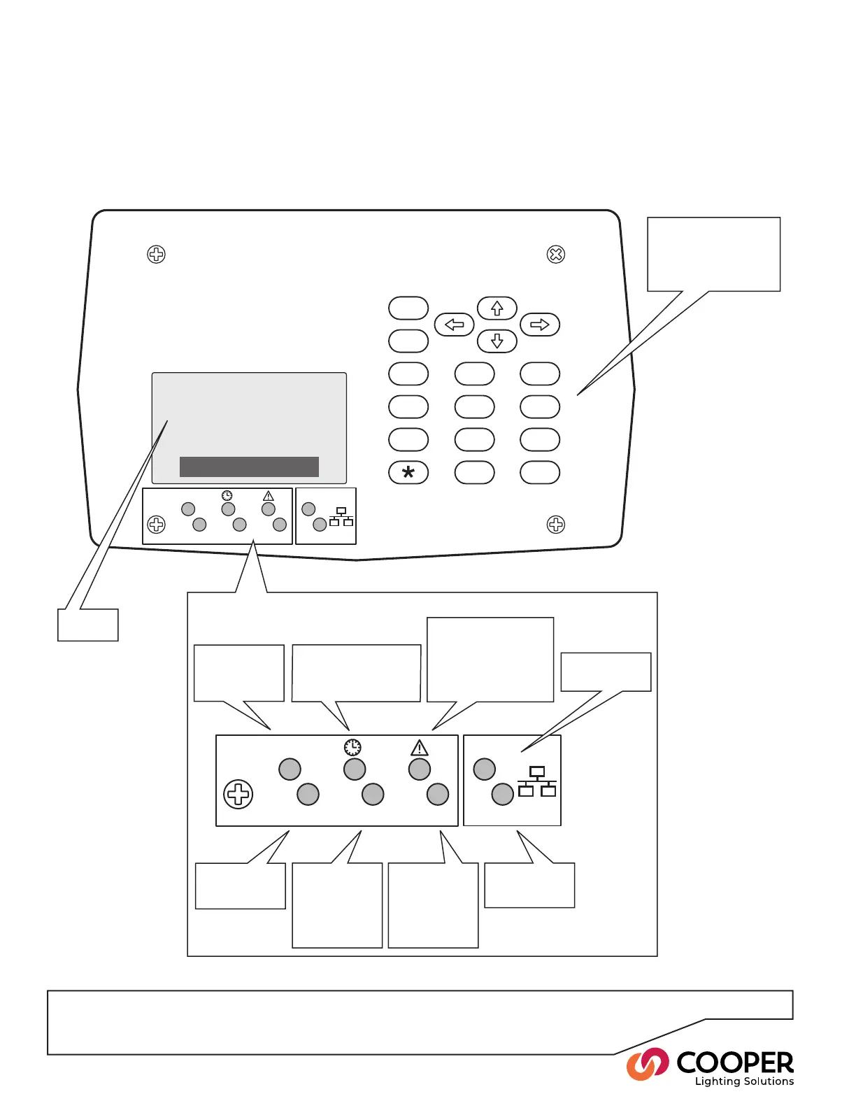
Basic Control Panel Operation
Using the Control Panel
Each Switched Relay Controller provides a control panel to make programming and operation as straightforward as
possible. To access the control panel, open the main panel door on the front of the unit.
ESC
12
0
ENT
3
456
789
#
iCAN
DMX
485
DATA
OK LINK
Device
255-129
Numeric keypad for
menu navigation
Clear text
display
Flashes when
data is present
on iCANbus link
iCAN
DMX
485
DATA
OK LINK
On when DMX
link is enabled,
ashes when
data is present
on
DMX link
Flashes when
data is present
on RS485 link
Flashes when
data is present
on Ethernet link
Flashes regu-
larly to indicate
correct system
operation
On when valid
Ethernet link
detected
Link and status indicators
When On, indicates that
the timeclock function is
enabled.
Illuminates when an
error condition occurs.
The display screen
will provide further
information about the
nature of the fault
21:56
August 14, 2008
Cooper Lighting Solutions