Operation Manual Page 15
A.2.3 Connecting the Power Source
The power connector and the main power switch are located at the right side of the back
of the document bed.
Important: Before connecting to the power source, check the following items:
The wall outlet is in perfect condition and properly grounded.
The power cable is not damaged in any way.
The wall outlet fuse has the correct electrical dimensions. Refer to the
technical specification chart for detailed information.
Check the device fuse. Use only the specified device fuse. The device fuse
specification is named on the identification plate.
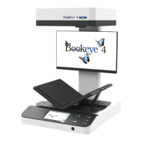
After the main power switch is turned on, the green START field above the START
button lights up. This indicates that the BOOKEYE Color is ready-to-use.
A.2.4 Connecting the Network
The Bookeye® 3 scanner is delivered with a cross-over cable (green cable connectors)
and a standard CAT6 network cable.
The network connector is located at the back side of the document bed.
Use the cross-over cable to connect the Bookeye® 3 scanner directly to a PC via a
network card.
Use the network cable to connect the Bookeye® 3 scanner to a network.
A.2.5 Connecting Foot Pedal Switches
The scan sequence and other operations can be invoked through the optional available
foot pedal switches.
At the back side of the device, there are two jack plugs to which the foot pedal switches
can be connected. The jack plugs are labeled with “FS1” and “FS2”.