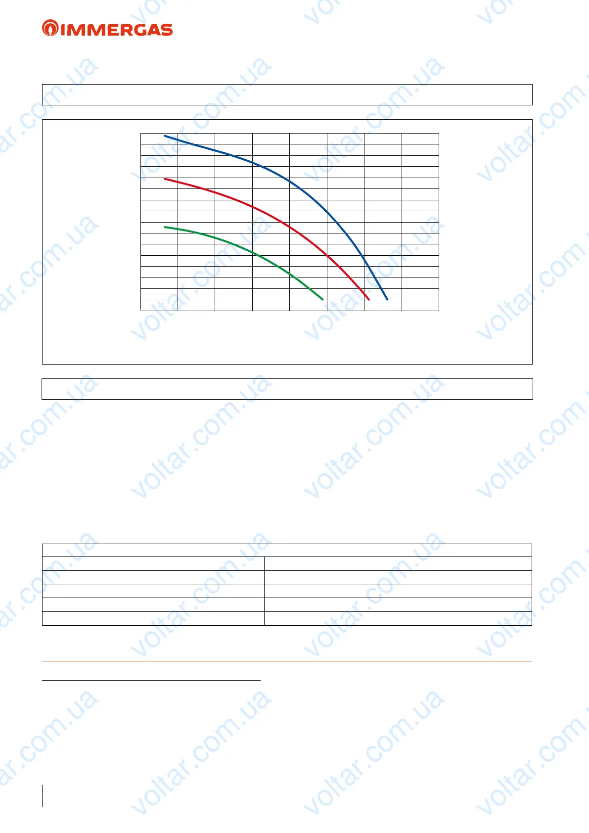
AUDAX TOP 12 ErP
44
15
20
25
30
35
40
45
50
55
60
65
70
75
80
85
90
95
0 500 1000 1500 2000 2500 3000 3500 4000
21 GRAPH OF AUDAX TOP 12 ErP PUMP FLOW RATE/HEAD
21.1 AUDAX TOP 12 ErP PUMP SETTINGS AND CONFIGURATIONS
Head (kPa)
Flow rate l/h
AUDAX TOP 12 ErP range boilers are supplied with a low power
consumption pump with variable speed control.
e pump's interface enables you to select between 6 pressure
levels with 2 types of controls:
• 3 constant pressure (CP) curves
• 3 proportional pressure (PP) curves
Constant Pressure Curve (CP) default setting. e circulator
pump maintains the pressure level (head) constant as the system
heat demand decreases (ow rate reduction). With these settings,
the pump is suitable for all oor systems.
Proportional Pressure Curve (PP) is allows the pressure level
(head) to be proportionally reduced as the system heat demand
decreases (ow rate reduction). anks to this function, the
electric power consumption of the circulator pump is reduced
further: the energy (power) used by the pump decreases according
to the pressure level and ow rate. With this setting, the pump
guarantees optimal performance in most heating systems, prov-
ing particularly suitable in single-pipe and two-pipe installations.
TECHNICAL NOTE: System minimum water content:
To facilitate proper execution of the AUDAX TOP ErP heat pump defrost cycles, a minimum water content in the system is required,
which must be: 6 l/kW of the machine's power for any type of system. e ywheel guarantees normal operation of AUDAX TOP ErP
with systems divided into zones (with variable water content in circulation). e ywheel also guarantees proper operation with fan coils
used for cooling (a condition in which the ow temperature is very low and has signicant heat load variations that vary the number of
active fan coils). It is also important to check that the dehumidier line has a minimum of 3 l/kW of the machine (dehumidier hydraulic
circuit connection).
N.B.: for inertial tanks codes supplied by Immergas, refer to page 107.
Setting procedure:
1) Factory setting Constant Pressure Curve CP3
2) Press the button for 10 seconds e pump goes into setting mode - the LED starts ashing
3) Each time it is pressed, the settings change LED “I”, “II”, and “III” are lit / the control curve and mode change
4) 10 seconds after the button is not pressed e setting is changed - the pump goes back to operating mode
5) LED “I” or “II” or “III” is still lit e pump is operating with the selected mode and curve.
All curves have been dened in constant pressure mode with minimum, intermediate and maximum speed.
voltar.com.ua
voltar.com.ua
voltar.com.ua
voltar.com.ua
voltar.com.ua
voltar.com.ua
voltar.com.ua
voltar.com.ua
voltar.com.ua
voltar.com.ua
voltar.com.ua
voltar.com.ua
voltar.com.ua
voltar.com.ua
voltar.com.ua
voltar.com.ua
voltar.com.ua
voltar.com.ua
voltar.com.ua
voltar.com.ua
voltar.com.ua
voltar.com.ua
voltar.com.ua
voltar.com.ua

 Loading...