AUDAX TOP ErP
25
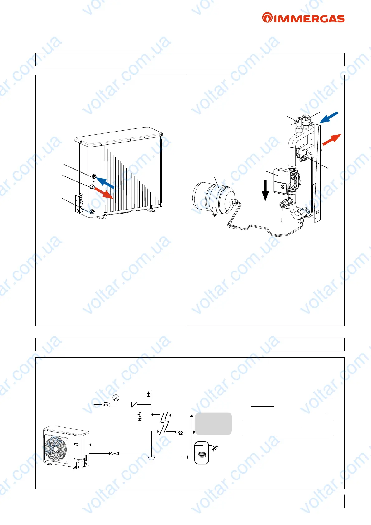
8 AUDAX TOP 6 8 ErP HYDRAULIC CIRCUIT COMPONENTS
1
2
4
7
3
5
1
2
3
KEY:
1 - System return tting 1"M
2 - System ow tting 1"M
3 - Water drain
KEY:
1 - Automatic air vent valve
2 - Flow switch
3 - Safety valve (outlet 1/2’)
4 - Temperature probe
5 - Circulation pump
7 - Expansion vessel
8.1 AUDAX TOP 6 8 ErP HYDRAULIC DIAGRAM
KEY:
1 - Shut-o valve
2 - Water line lters (standard)
3 - Pressure gauge (not supplied - to be
provided)
4 - Filling valve (NOT Automatic)
5 - System draining valve (in the lowest
points of the circuit)
6 - Air vent valve (in the highest points
of the circuit)
7 - 3-way valve
8 - DHW storage tank
9 - Internal utility
e diagram is purely indicative and not limited to the hydraulic circuit.
Also see the example on page 90-91
1
1
2
3
3
4
6
5
7
8
9
voltar.com.ua
voltar.com.ua
voltar.com.ua
voltar.com.ua
voltar.com.ua
voltar.com.ua
voltar.com.ua
voltar.com.ua
voltar.com.ua
voltar.com.ua
voltar.com.ua
voltar.com.ua
voltar.com.ua
voltar.com.ua
voltar.com.ua
voltar.com.ua
voltar.com.ua
voltar.com.ua
voltar.com.ua
voltar.com.ua
voltar.com.ua
voltar.com.ua
voltar.com.ua
voltar.com.ua

 Loading...