AUDAX TOP ErP and Integrated System
88
12
10
8
11
9
13
14
15
2
19
4
1
17
18
16
7
3
5
6
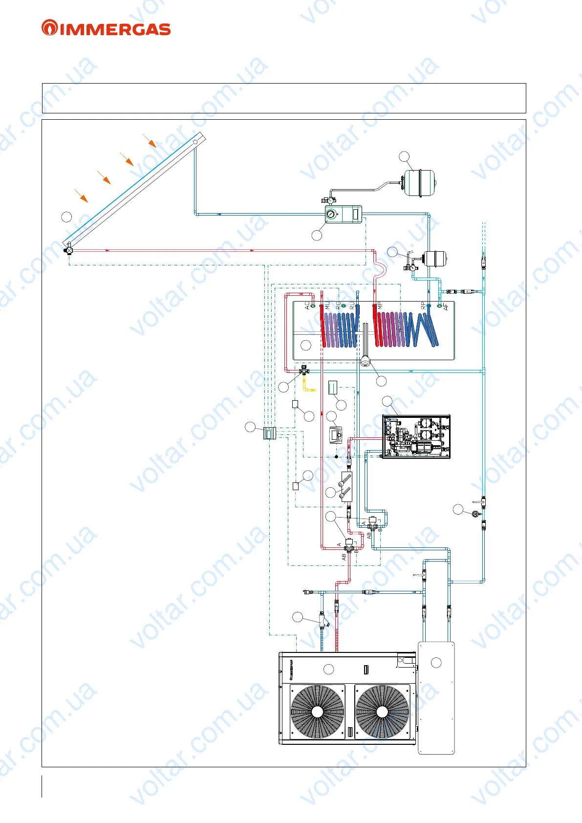
48 HYDRAULIC DIAGRAM: AUDAX TOP ErP and 2 low temperature zones
+ SOLAR HEATING for DHW + SYSTEM MANAGER
KEY:
1 - AUDAX TOP 16 ErP
2 - Integrative resistance for heating system kit (selectable powers: 2 - 4 - 6 kW)
3 - M/XL CP4 solar manifold
4 - Double coil storage tank unit
5 - Solar ErP circulation unit with safety valve
6 - Solar expansion vessel
7 - Expansion valve and safety valve for DHW
8 - 2 mixed zones kit (including expansion boards for zone management)
9 - Integrative resistance for 2 or 5 kW storage tanks
10 - Temperature/humidity sensor
11 - DHW thermostatic mixer
12 - System Manager
13 - DHW resistance enabling relay (EMR 12 Vdc)
14 - 3-way diverter kit
15 - Heating system resistance enabling relay (SSR 6 Vdc)
16 - Standard "Y" lter for AUDAX TOP ErP
17 - Inertial storage tank
18 - Control Panel (standard)
19 - System pressure gauge (to provide)
NOTE: this diagram is an example. It is also required to convey the heat pump's condensate drain.
In order to guarantee proper Heat Pump operation (also with antifreeze), each system must consider inserting a bypass to guarantee a minimum ow rate of 420 l/h. In this diagram, the bypass is already
installed in the zones kit (8).
voltar.com.ua
voltar.com.ua
voltar.com.ua
voltar.com.ua
voltar.com.ua
voltar.com.ua
voltar.com.ua
voltar.com.ua
voltar.com.ua
voltar.com.ua
voltar.com.ua
voltar.com.ua
voltar.com.ua
voltar.com.ua
voltar.com.ua
voltar.com.ua
voltar.com.ua
voltar.com.ua
voltar.com.ua
voltar.com.ua
voltar.com.ua
voltar.com.ua
voltar.com.ua
voltar.com.ua

 Loading...