AUDAX TOP ErP and Integrated System
102
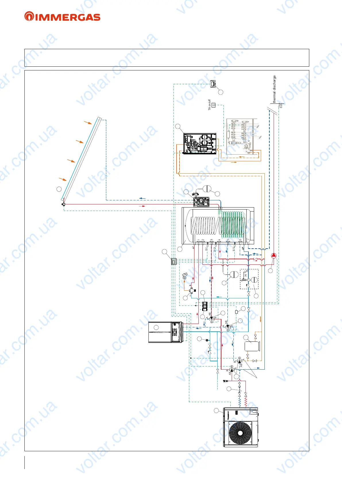
55 HYDRAULIC DIAGRAM: AUDAX TOP
ErP
+ BOILER and 2 low temperature zones
+ SOLAR HEATING for DHW and C.H. + SYSTEM MANAGER
NOTE: this diagram is an example. It is also required to convey the condensate drain of the heat pump and boiler.
In order to guarantee proper Heat Pump operation (also with antifreeze), each system must consider inserting a bypass to guarantee a minimum ow rate of 420 l/h.
14 - 3-way valves boiler integration kit
15 - Boiler integration 3-way valve enabling relay
16 - Heating system expansion vessel
17 - Expansion valve and safety valve for DHW
18 - Heating system circulation pump
19 - Inertial storage tank (for cooling operation)
20 - 3-way valve kit for hot/cold system switch-over
21 - Standard "Y" lter for AUDAX TOP ErP
22 - System pressure gauge (to provide)
KEY:
1 - AUDAX TOP 6-8 ErP
2 - VICTRIX TT / kW TT PLUS / MAIOR TT
PLUS
3 - XL CP4 solar manifold
4 - DHW + C.H. combined storage tank unit
5 - Solar ErP circulation unit with safety valve
6 - Solar expansion vessel
7 - 2 mixed zones kit (including expansion
boards for zone management)
8 - Control Panel (standard)
9 - System Manager
10 - DHW thermostatic mixer
11 - Expansion board address 4 to manage the
request for boiler and DHW central heating
12 - Expansion board address 5 for thermal dis
-
charge
13 - DHW 3-way priority valves
Flow/Return system with hot or cold
heat transfer uid
F/R sytem with
cold uid
F/R system with
hot uid
3
20
17
16
6
5
7
9
11
14
4
10
Water-D.H.W. network
19
12
18
8
13
15
1
21
22
2
voltar.com.ua
voltar.com.ua
voltar.com.ua
voltar.com.ua
voltar.com.ua
voltar.com.ua
voltar.com.ua
voltar.com.ua
voltar.com.ua
voltar.com.ua
voltar.com.ua
voltar.com.ua
voltar.com.ua
voltar.com.ua
voltar.com.ua
voltar.com.ua
voltar.com.ua
voltar.com.ua
voltar.com.ua
voltar.com.ua
voltar.com.ua
voltar.com.ua
voltar.com.ua
voltar.com.ua

 Loading...