18
INSTALLER
USERMAINTENANCE TECHNICIAN
TECHNICAL DATA
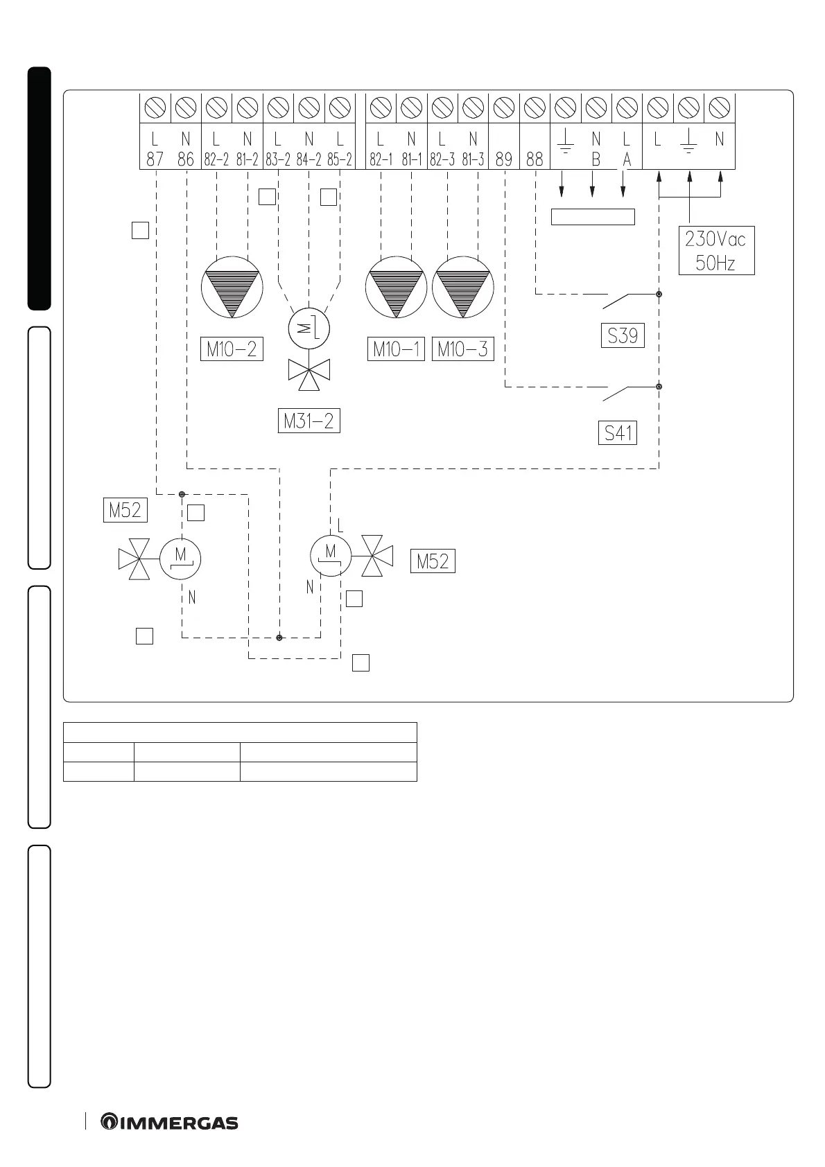
Low voltage electrical connection diagram.
1
2
3
1
1
4
5
6
10
Ter m ina l 87
0V Close Winter
230V Open Summer with cooling
Key (Fig. 10):
1 - Open/Close
2 - Close
3 - Open
4 - Valve with spring return
5 - valve with 2 points
6 - Auxiliaries
M10-1 - Zone 1 pump (optional)
M10-2 - Zone 2 circulator pump (optional)
M10-3 - Zone 3 circulator pump (optional)
M31-2 - Zone 2 mixing valve (optional)
M52 - Hot cold three-way (optional)
S39 - Solar inlet
S41 - Outdoor unit deactivation
A 3rd zone (mixed) can also be managed on the system by means
of the congurable relay interface kit (optional).
In this case, the zone 3 pump must be connected according to dia-
gram (M10-3).
e zone 3 dehumidier, if any, will be managed by means of the
congurable relay interface kit, which the zone 3 mixer will also
be connected to.

 Loading...


