19
INSTALLER
USERMAINTENANCE TECHNICIAN
TECHNICAL DATA
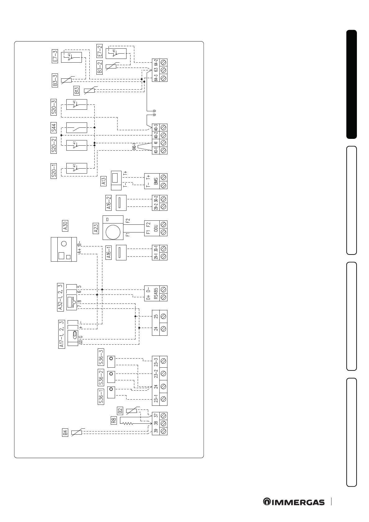
Electrical connection diagram (very low voltage).
11
A16-1 and A16-2 dehumidiers can be connected only aer in-
stalling 2-relay board (optional).
Remove jumper X40-1 before the electrical connection of the
r o o m t h e r m o s t a t z o n e 1.
Key (Fig. 11):
A13 - System manager (optional)
A16-1 - Zone 1 dehumidier (optional with dehumidier
management board)
A16-2 - Zone 2 dehumidier (optional - with dehumidier
management board)
A17-1 - Zone 1 humidity sensor (optional)
A17-2 - Zone 2 humidity sensor (optional)
A17-3 - Zone 3 humidity sensor (optional)
A23 - External unit
A30 - Dominus
A32-1 - Zone 1 remote panel (optional)
A32-2 - Zone 2 remote panel (optional)
A32-3 - Zone 3 remote panel (optional)
B2 - Storage tank probe (optional)
B3-2 - Zone 2 ow probe (optional)
B3-3 - Zone 3 ow probe (optional)
B4 - External probe (optional)
B13 - Central heating probe (optional)
E7-2 - Mixed zone 2 safety thermostat (optional)
E7-3 - Mixed zone 3 safety thermostat (optional)
R8 - Storage tank resistance
S20-1 - Zone 1 room thermostat (optional)
S20-2 - Zone 2 room thermostat (optional)
S20-3 - Zone 3 room thermostat (optional)
S36-1 - Zone 1 humidistat (optional)
S36-2 - Zone 2 humidistat (optional)
S36-3 - Zone 3 humidistat (optional)
S44 - Heating / Cooling selector
X40-1 - Zone 1 room thermostat jumper

 Loading...


