iNetVu
®
Mobile Installation Manual Page 31 of 93
6. Slide the Mobile Platform over to the center of the roof using a tape measure.
7. Mark a “foot print” or outline of the Mobile Platform onto the vehicle’s roof using chalk
or non-permanent marker.
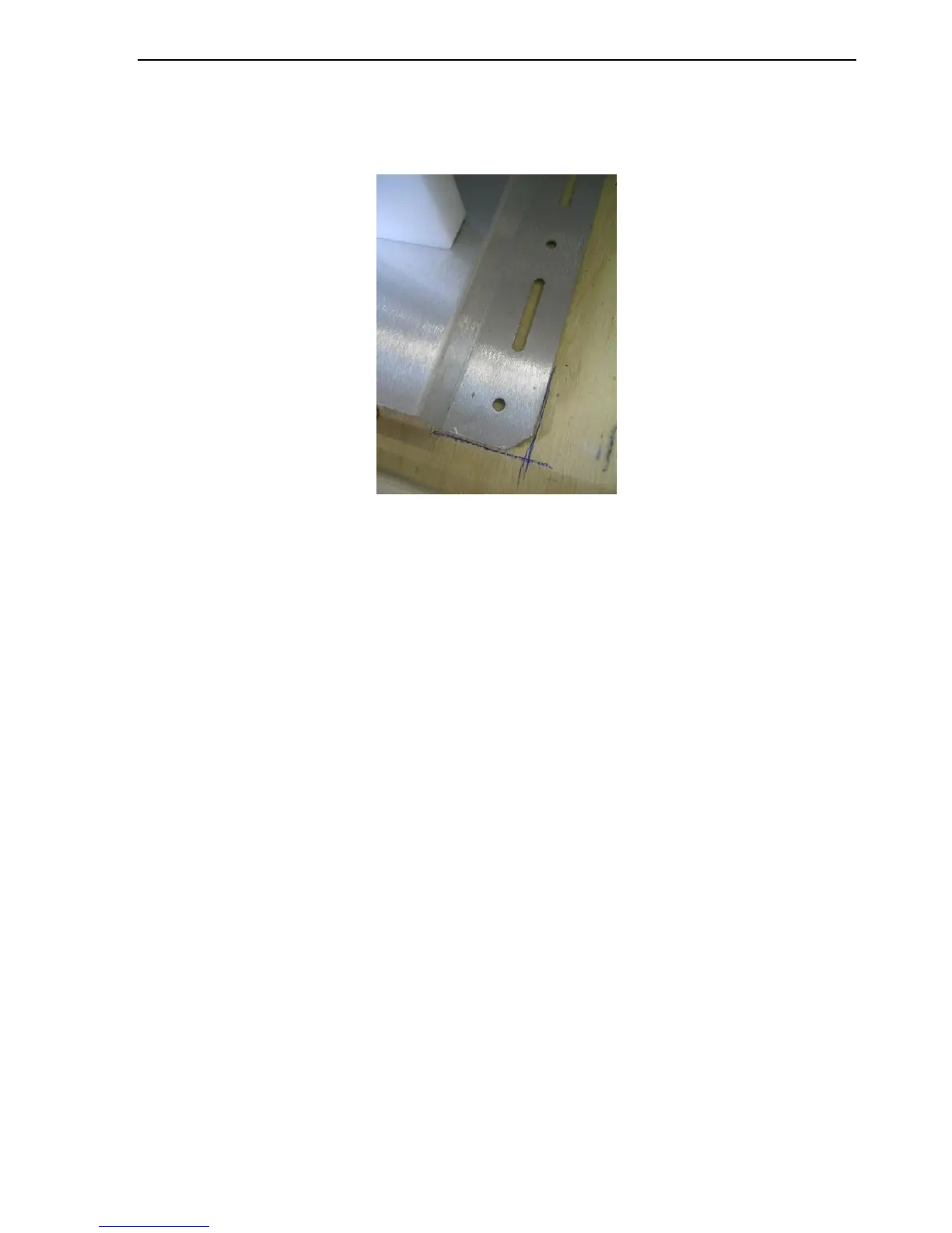
Fig. 12: Marked outline of an iNetVu® Mobile Platform
8. Verify that the roof is flat within 1/16” (1.6mm).
Note: If the roof surface is not flat within 1/16” (1.6mm), apply a thin layer of structural
epoxy grout between the base and vehicle surface. Snug the bolts finger tight and
allow epoxy to cure before the final torque-down.
9. Drill the appropriate sized pilot holes for the roof type (if required)
Fiberglass: Required. Regular (non-self-tapping) stainless steel screws.
Rubber-covered metal: Not required. Self-tapping, stainless steel screws
Aluminum: Not required. Self-tapping, stainless steel screws.
If pilot holes are required, the dimensions on the following CAD drawing can be
utilized. The hole sizes shown are the Mobile Platform (clearance) holes. The holes to
be drilled for self-tapping screws will require a smaller diameter. Ensure the roof top
is capable of handling the iNetVu System load, prior to installation. C-COM
Satellite Systems Inc. does not hold responsibility to any damage caused by
direct roof installations.