iNetVu
®
Mobile Installation Manual Page 40 of 93
3.7 iNetVu
®
Mobile System Wiring
The System wiring varies upon the type of controller and modem used. See the iNetVu
TM
Service Manual for a detailed system-wiring diagram and explanation.
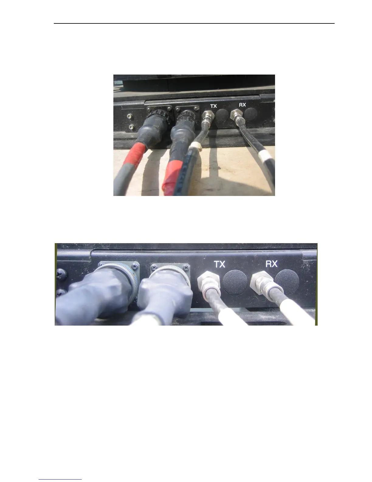
Fig. 21: From left to right: Sensor Cable, Motor Control Cable, Tx and Rx RG6 Coaxial Cables
Military Style Connectors
Fig. 22: From left to right: Motor Cable, Sensor Cable, Tx and Rx RG6 Coaxial Cables