Installation Manual
Powering up the system 45
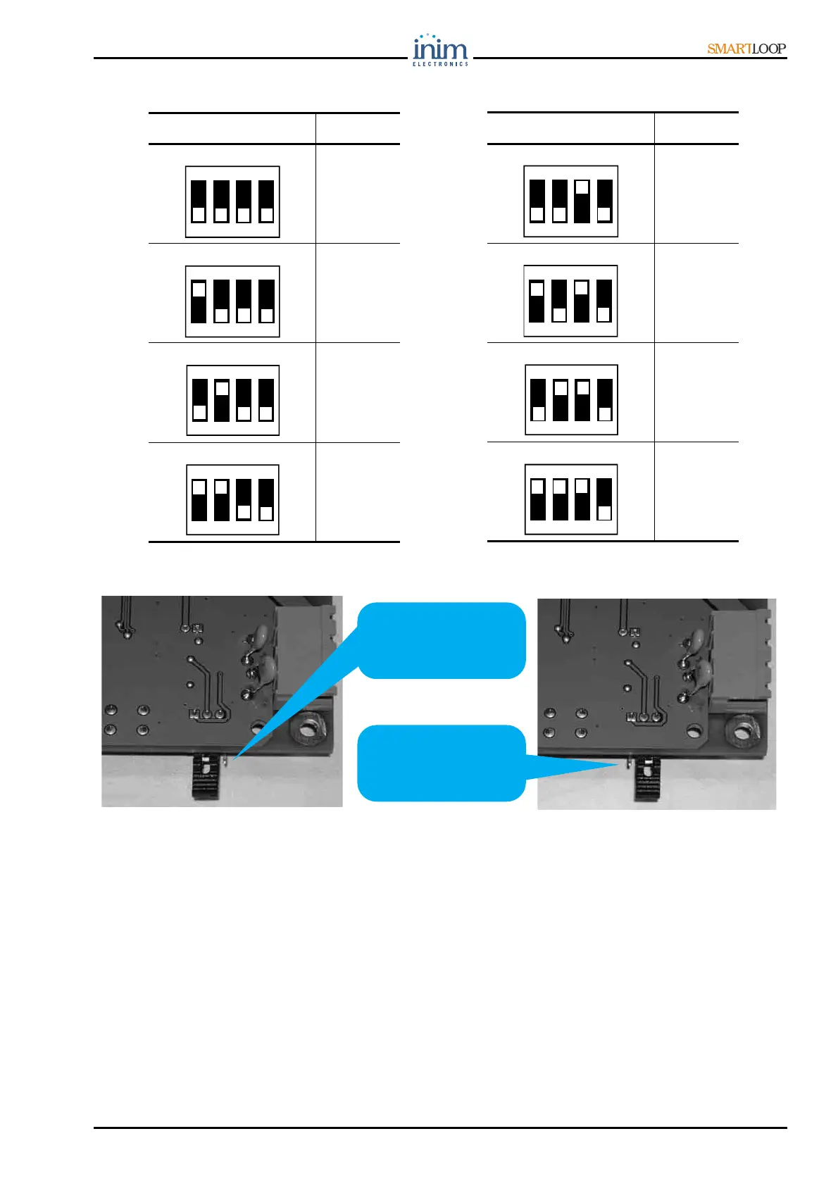
7. Check that the EOL resistance jumper [figure 42] is in the EOL position on the last Repeater panel
only.
Figure 42 - Jumper position
8. If several panels are connected in a token-ring network, check the integrity of the ring, as follows:
• Extract the network terminal boards [figure 9-2,6] from the SmartLoop/NET board of one of the
panels, and check the continuity of wiring in the D+ circuit (between D+ poles of ports A and B),
and the D- circuit (between D- poles of ports A and B).
Posizione Dip Switch Indirizzo
5
6
7
8
ON
1 2 3 4
ON
1 2 3 4
ON
1 2 3 4
ON
1 2 3 4
Jumper position for
other Repeaters
Jumper in EOL
position for the
last Repeater
Posizione Dip Switch Indirizzo
1
2
3
4
ON
1 2 3 4
ON
1 2 3 4
ON
1 2 3 4
ON
1 2 3 4