Installation Manual
46 Powering up the system
8.1.1 First power up
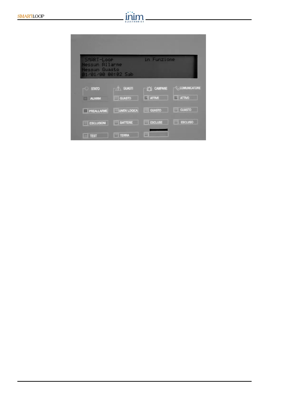
Figure 43 - First power up
1. Insert the “SAVE” jumper [figure 5-7] (data retention is guaranteed by the 2032 lithium battery).
2. Using the battery terminal eyelet wires (one at each end), connect the 17Ah batteries together,
the positive of one battery to the negative of the other [figure 38].
3. Connect the battery to control panel terminal eyelets wires (included), insert the battery terminal
bolt through the spacer washer and battery terminal eyelet tab, observe the polarity (red to
positive, black to negative).
Using the same wire, connect the batteries to the control panel motherboard. Observe the connector
polarity [figure 5-21].
4. The panel will take several seconds to stabilize.
5. After approximately 2 minutes, the panel will signal a Mains Power fault (Fault LED and Mains LED
On). The CPU FAULT LED will blink to indicate board activation.
6. Power the panel from the mains. The Mains fault (if active) will clear (MAINS POWER LED will go Off)
but the yellow fault LED (FAULT LED) will retain fault memory until manually reset.
7. If at this point the panel signals other faults, check the wiring integrity and clear all faults before
continuing (refer to “Troubleshooting” on page 47).
8. Once all fault conditions have been cleared, turn the key in the keyswitch to access Level 2 (refer
to “Operator authorization—access levels” on page 9) then press RESET. All LEDs, except for the
green ON LED should go Off and the panel display should show
No Alarm, No Fault.
9. Press the TEST button to check the integrity of the LEDs.