Commissioning and Trial Run
‑41‑
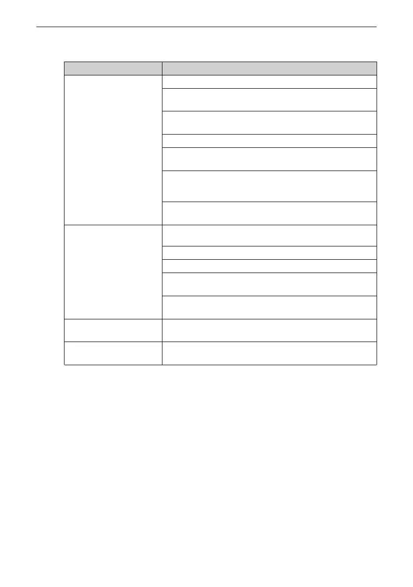
Table 2–2 Check items before power‑on
Item
Description
Main circuit wiring
The power supply voltage is correct (380–480 VAC; 50/60 Hz).
The power supply input terminals and the AC drive input
terminals (R/S/T) are connected properly.
The motor input terminals and the AC drive output terminals
(U/V/W) are connected properly.
The AC drive and motor are properly grounded.
The dimensions of the main circuit cables meet the
requirements.
Heat‑shrink tubes have been applied to the copper lugs and
conductors of the main circuit cable and completely wrap
the cable conductors.
The motor output cable does not exceed 50 m. Otherwise,
the carrier frequency needs to be reduced through F0‑15.
Control circuit wiring The control circuit terminals are reliably connected to other
control devices.
The control circuit cables are shielded twisted pairs.
Optional cards are connected correctly.
Control circuit cables and main circuit cables are routed
separately.
The control circuit terminals of the AC drive are all in the OFF
state (the AC drive is not running).
Load The motor is in the no‑load state and is not connected to any
mechanical system.
Braking resistor The braking resistor and braking unit are wired properly with
proper resistance values.
2.2.2 Power-On
Close the power supply switch and check the display on the operating panel of the AC
drive. If the operating panel displays 50.00, the AC drive is powered on.

 Loading...


