Commissioning Tools
‑28‑
different faults, whereas pressing the left/right key can switch among different
menus.
2. Parameters in the primary display area
When the AC drive is running, you can press
or to view status parameters.
The status parameters displayed by default include running frequency, frequency
reference, bus voltage, output voltage, and output current. For more status
parameters, see descriptions of F7‑03 and F7‑04 in "Related Parameters".
When the AC drive is in the stop state, you can press
or to view the status
parameters. The status parameters displayed by default include frequency
reference, bus voltage, AI1 voltage, and AI2 voltage. To view more status
parameters, see descriptions of F7‑05 in "
1.2 Related Parameters
"
on page 21
.
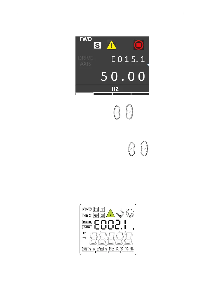
1.6 Display of Faults and Alarms
When a fault occurs on the AC drive, the fault indicator turns on, and the secondary
display area displays a fault code, as shown in the following figure.
Figure 1‑6 Fault code display

 Loading...


