4 HCU Control Module
- 90 -
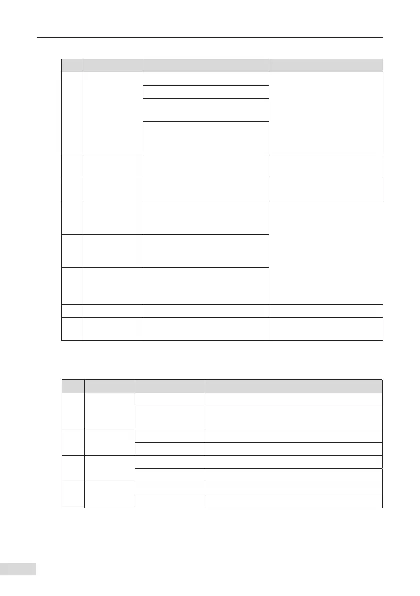
Table 4-6 Descriptions of HPCU-40/60 components
No. Name Description Description
1
Input power
supply
COM: 24 V GND
External power supply of HPCU
X1 terminal: 5.08 mm pitch,
4-pin black pluggable terminal
Twisted pair cable
Cross sectional area: 0.5–2.5
mm
2
COM: 24 V GND
24VA:
Input power A 24.0 V±10% 0.5 A
24VB:
Input power B (redundant design)
24.0 V±10% 0.5 A
2 LED indicator PWR/BAT/TX/RX
Power/battery indication/send/
receive
3
Battery DIP
switch
S2: BAT_SW Reserved
4
Optical ber
transceiver
VT/VR:
CH1–CH4, parallel module channel
1–channel 4
VT: 50 M, transmit optical ber
communication signals
VR: 50 M, receive optical ber
communication signals
Optical ber type: plastic
optical ber (POF)
HPCU-40 contains channels:
CH1–CH4
HPCU-60 contains channels:
CH1–CH6
5
Optical ber
transceiver
VT/VR:
CH5/CH6, parallel module channel
5–channel 6
6
Optical ber
transceiver
VT/VR:
HCU Inodrive, communication
between HPCU and HCU
7 LAN PC control terminal -
8 Fixing hole
Holes for xing the HPCU.
Quantity: 4
-
4.8.2 LED Indicators
Table 4-7 Description
No. Name Status Function
1 PWR
Steady on in green The HPCU power supply is normal.
OFF
The HPCU is not energized or the power supply
has failed.
2 RUN
Steady on in green The AC drive is running.
OFF The AC drive stops.
3 FAU
Flashing in red A system fault occurs.
OFF The system is normal.
4 BAT
Steady on in red Battery undervoltage
OFF The battery is normal.

 Loading...


