3 Electrical Installation
- 76 -
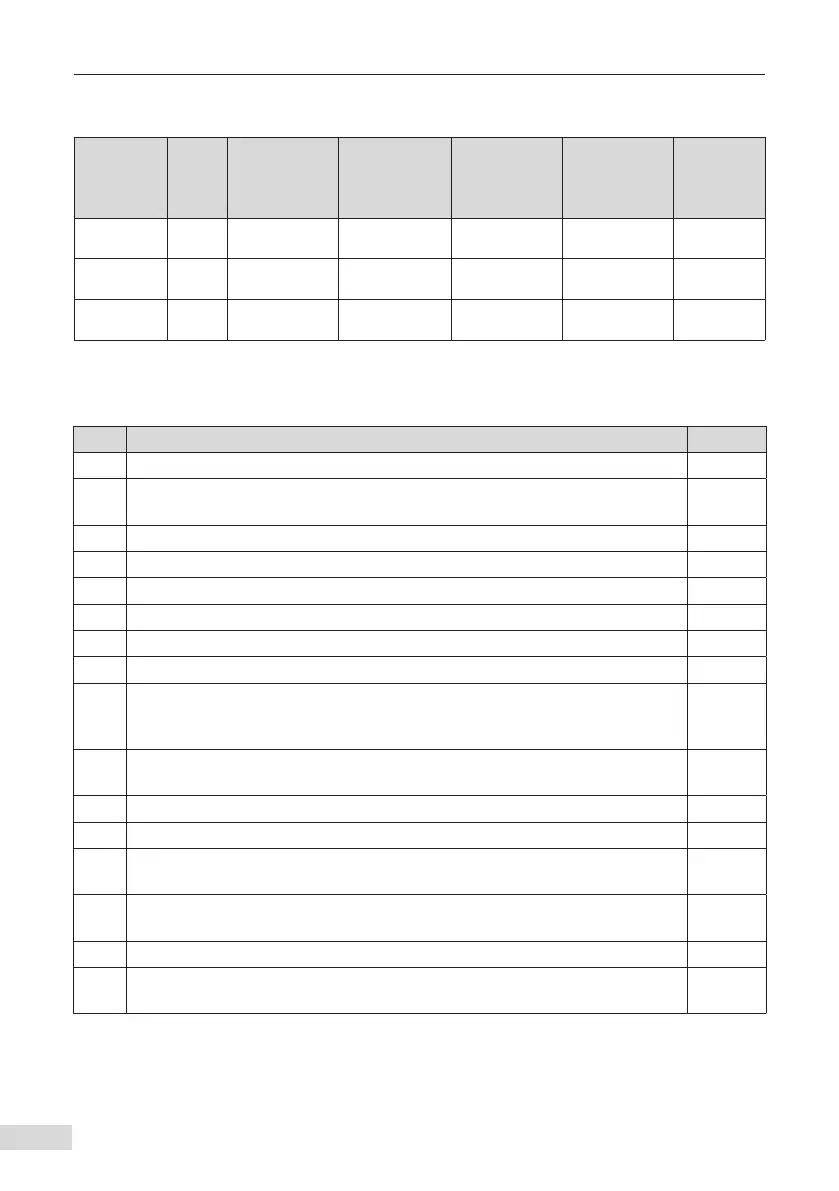
Table 3-13 Main circuit cable selection for MD880-01S-0673-4-(L)/MD880-01S-0751-4-(L)/
MD880-01S-0849-4-(L)
AC Drive
Model
Rated
Current
(A)
Recommended
Input/Output
Power Cable
(mm
2
)
Recommended
Lug Model
Recommended
Grounding
Cable (mm
2
)
Recommended
Grounding
Cable Lug
Model
Tightening
Torque
(N·m)
MD880-01S-
0673-4-(L)
673 2 x (3 x 185) BC185-16 185 BC185-16 85.0
MD880-01S-
0751-4-(L)
751 2 x (3 x 185) BC185-16 185 BC185-16 85.0
MD880-01S-
0849-4-(L)
849 2 x (3 x 240) BC240-16 240 BC240-16 85.0
3.6 Wiring Checking
Table 3-14 Wiring checking
No. Item Checked
1 Whether the AC drive model is consistent with that on the order □
2
Whether peripherals (braking resistors, braking units, AC reactors, lters, and
circuit breakers) meet design requirements
□
3 Whether the installation method and location of the AC drive meet requirements □
4 Whether the AC drive input voltage is in the range of 323 V to 528 V □
5 Whether the rated motor voltage is consistent with the AC drive output voltage □
6 Whether power input cables are connected to the R, S, and T terminals □
7 Whether motor input cables are connected to the U, V, and W terminals □
8 Whether cable diameter of the main circuit meets requirements □
9
Whether heat shrink tubes are added to cable lug copper tubes and cable core
parts of main circuit cables and the heat shrink tube completely covers the
cable conductor part
□
10
Whether the motor output cable is longer than 50 m. If yes, reduce the carrier
frequency.
□
11 Whether the grounding cable is connected correctly □
12 Whether the AC drive output terminals are secure □
13
Whether the braking resistor and braking unit (if used) are connected correctly
and whether their resistance is correct
□
14
Whether the shielded twisted pair (STP) is used as the signal cable of the AC
drive control circuit
□
15 Whether the optional card is connected correctly □
16
Whether the control circuit cable and main circuit power cable are routed
separately
□

 Loading...


