4 HCU Control Module
- 82 -
■
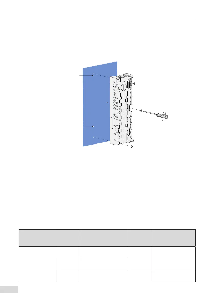
Installing the HCU for AC drives of structures T10 to T12
1) Align the HCU vertically with the two positioning holes on the metal mounting
plate.
2) Tighten the HCU mounting screws with a 1# Phillips screwdriver (three M4 screws
are already xed in the HCU) as shown below.
.FUBMNPVOUJOH
QMBUF
1PTJUJPOJOHIPMF
Figure 4-4 Installing the HCU
■
Grounding inside the cabinet
The mounting plate of the HCU must be a bare metal plate and reliably grounded.
The HCU housing will be grounded to the cabinet housing through the screws on the
mounting surface.
4.4 Function Module
The HCU can be used with other function modules to expand its functions. Specic
information is as follows:
Table 4-3 Function modules used with HCU
Name Model Function
Connection
Method
Dimensions
(Length x Width x
Height, mm)
Encoder detection
module
HPG-10
HTL incremental encoder
signal detection
SLOT 105 x 73 x 24
HPG-40
Resolver encoder signal
detection
SLOT 105 x 73 x 24
HPG-50
TTL incremental encoder
signal detection
SLOT 105 x 73 x 24

 Loading...


