19
System Description and Terminology
Product Support: www.instron.com
Principle of Operation
The system communicates primarily through the controller. The controller contains
sensor conditioning cards for the system transducers and transfers data between the
transducers and the computer. The controller also communicates with the load frame
via a Safety Monitoring Board (SMB) via a Break Out Board (BOB) inside the load frame.
The Break Out Board links all the electrical components of the frame together.
Hardware Controls
The hardware controls consist of:
• Emergency stop button - to be used whenever you need to stop the crosshead
immediately because an unsafe condition exists.
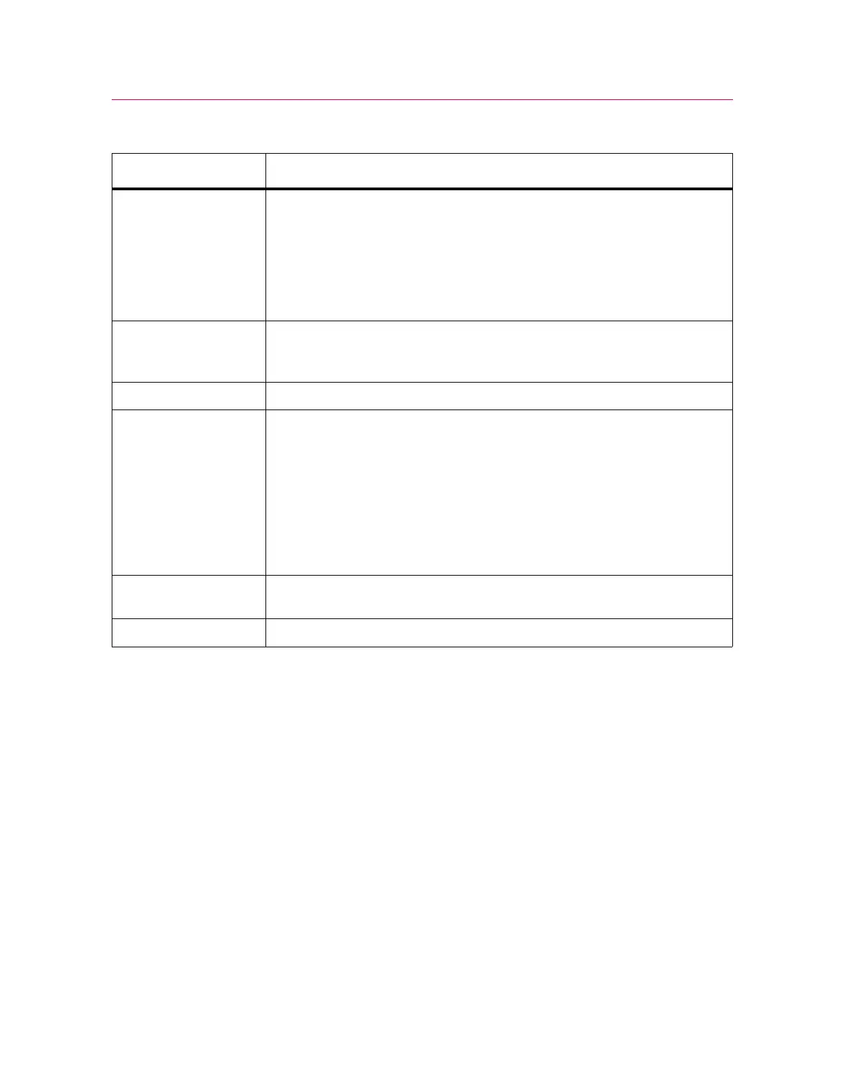
Table 1. Testing System Components
Component Description
Load Frame The load frame comprises a base, one or two columns, a moving crosshead,
and a top plate. It is a high stiffness support structure against which the test
forces react.
Each column comprises a guide column and a ballscrew. The crosshead is
mounted on both the guide column and the ballscrew. Rotation of the
ballscrew drives the crosshead up or down while the guide column provides
stability.
Controller The hardware that controls the frame and any ancillary equipment connected
to the testing system. The controller panel contains all the connectors for load
cells, extensometers and any other sensors that are required for testing.
Frame Control Panel This panel holds all of the controls and indicators for the testing system.
Load String Comprises all of the components that you install between the moving
crosshead and the load frame base (or fixed crosshead). Typically this involves
a load cell, a set of grips, any adapters that are required to connect the
components, and the specimen to be tested.
Typically, you mount a load cell on the crosshead, then a pair of grips or
fixtures on the load cell and frame base. The grips or fixtures secure the
specimen and when you start a test the crosshead moves up or down applying
a tensile or compressive load to the specimen. The load cell converts this load
into an electrical signal that the software measures and displays.
Bluehill
®
Software Instron
®
testing software that controls the testing system, running tests and
analyzing test data to produce test results.
Specimen A single piece of material to be tested.