EasyManuals Logo

Instron 34SC-1 User Manual

Default Icon
126 pages
To Next Page IconTo Next Page
To Previous Page IconTo Previous Page
Page #76 background imageLoading...
Page #76 background image
Chapter: Assemble the load string
76 M10-17313-EN
The crosshead is positioned below its travel midpoint so that you can easily and
safely access the crosshead.
The frame is in the disabled state, i.e. the white LED above the DISABLED indicator
on the frame control panel is illuminated.
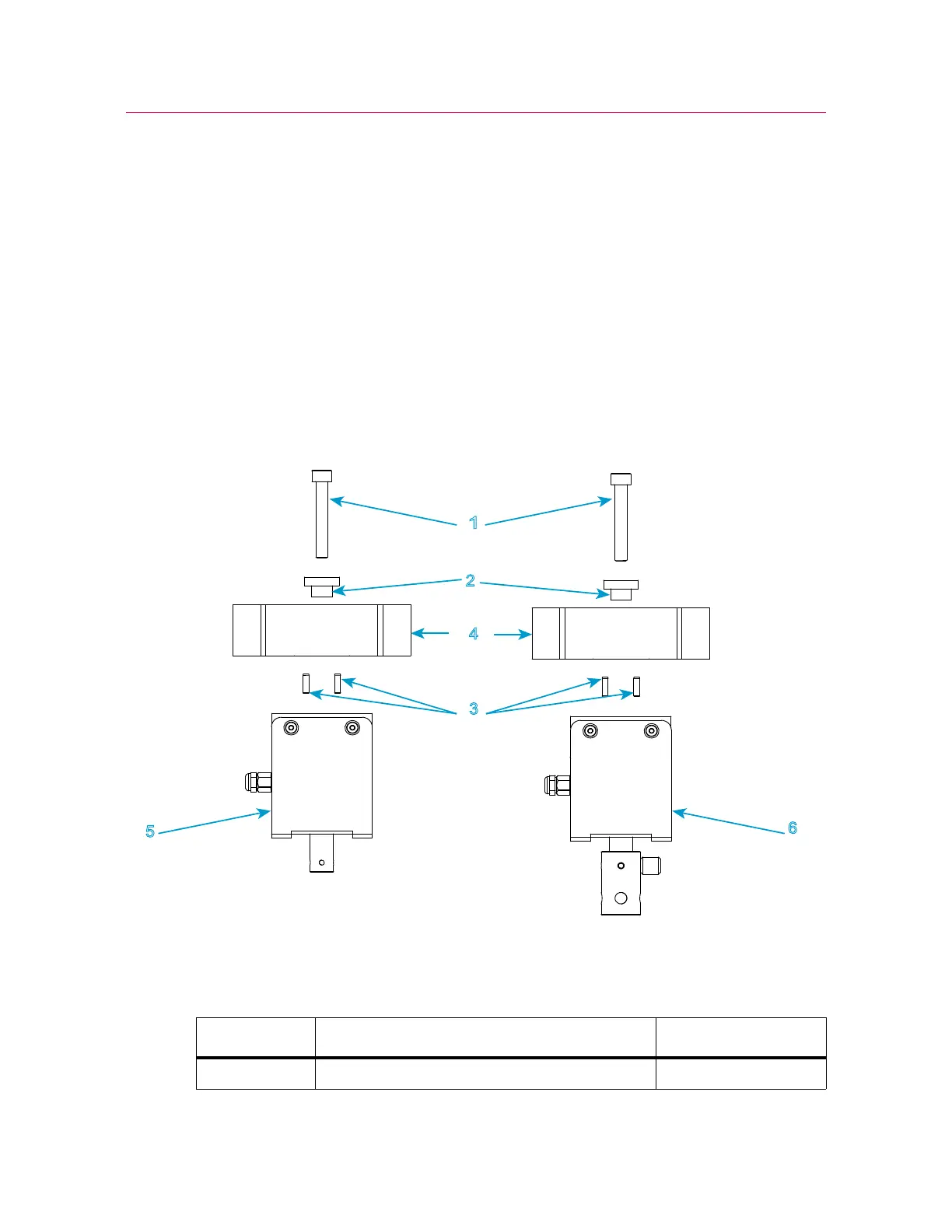
Install the load cell
Install a 2519 load cell (capacities 10 N through 1 kN)
Figure 15. Install a 2519 series load cell - capacities 10 N through 1 kN
Legend for Figure 15
1
2
3
4
5
6
10N - 100N
500N - 1kN
Label Component Part number
1 Screw, M6 x 40 201V38

Table of Contents

Questions and Answers:

Question and Answer IconNeed help?

Do you have a question about the Instron 34SC-1 and is the answer not in the manual?

Instron 34SC-1 Specifications

General IconGeneral
BrandInstron
Model34SC-1
CategoryTest Equipment
LanguageEnglish

Related product manuals