Chapter: Function of controls
50 M10-17313-EN
Power input connector
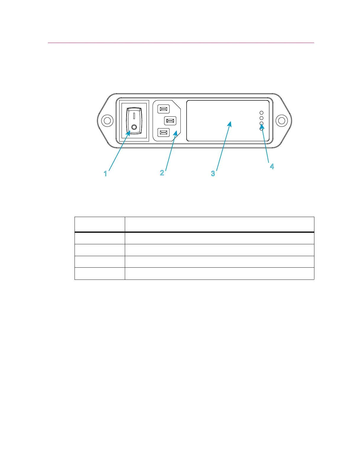
Figure 12. Power input connector
Legend for Figure 12
The power input connector, shown in Figure 12 on page 50, performs the following
functions:
• connects the load frame to the electrical power supply
• contains the ON/OFF switch
• holds the power fuses
• controls the voltage setting. The voltage setting can be changed if necessary, refer
to “Power supply compatibility” on page 32.
Refer to Figure 2 on page 17 to see the location of the power input connector on your
load frame.
Label Component
1Power switch
2IEC inlet connector
3 Fuse carrier and voltage selector access
4 Selected voltage