Chapter: Installation
34 M10-17313-EN
• Green and yellow - earth (ground)
Set the input voltage
The load frame voltage is factory set according to the voltage that was specified at the
time of purchase.
Use the following procedures only if the facility power source does not match the frame
voltage setting. This situation may arise if the system is moved to another location with a
different voltage rating from the factory setting on the frame.
Determine the voltage setting
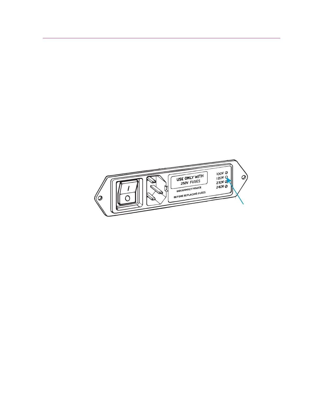
Figure 4. Power input connector with voltage setting
1. Locate the power input connector on the rear of the testing machine base.
2. Inspect the power input connector and refer to Figure 4 on page 34. There are four
holes in a vertical line at the right side of the connector, each corresponding to a
different line voltage. The current voltage is indicated by a white plastic pin visible in
one of the holes. The indicated voltage in Figure 4 is 120V.
Change the voltage setting
Use the following procedure only if the facility power source does not match the frame
voltage setting. This situation may arise if the system is moved to another location with a
different voltage from the factory setting on the frame.
You will need the following equipment (not supplied):
• Small flat-head screwdriver or probe
• Long-nose pliers