- 18 - - 19 -
Parts Nomenclature and Functions Parts Nomenclature and Functions
AppendixBefore use
1
Setting Up
2
Printing
3
Basic Device Operations
4
Index
AppendixBefore use
1
Setting Up
2
Printing
3
Basic Device Operations
4
Index
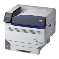
Back/Left Side
Interface
There are a LAN (network) interface connector and a
USB interface connector. See “Interface” (P.23) for
the interfaces.
Exit Unit
Open this when replacing the fuser unit or transfer
roller unit, or to clear paper jams.
Access Cover
Open this when mounting the optional built-in HDD.
Duplex Unit
Implements duplex printing.
Carrying Handles
Hold these at the same time as the carrying lever
when carrying the device.
Carrying Lever
When carrying the device, pull out this lever, and
hold the carrying handles at the same time.
Power Connector
Connect the enclosed power cable here.
Main Power Switch
Turns ON and OFF the device main power supply.
Left Side Cover
Open this to clear paper jams.
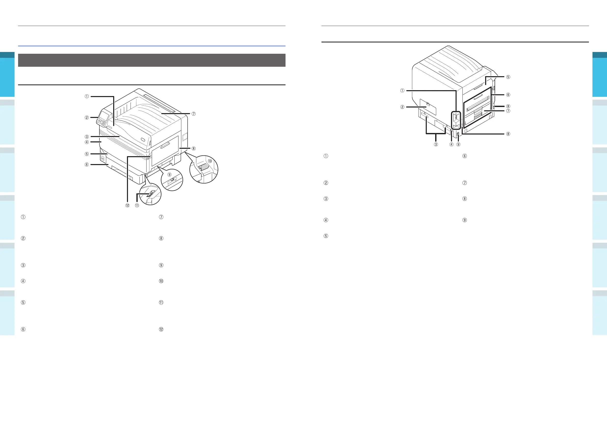
Parts Nomenclature and Functions
Main Unit
Front/Right Side
Toner Cover
Open this to replace the toner cartridge.
Face Down Stacker
The printed sheets are placed printed-side down and
discharged.
Control Panel
Displays the device status and menus, and sets the
functions.
“Control Panel” (P.24)
Right Side Cover
Open this to replace the multi-purpose tray feed
roller, and to clear paper jams.
Front Lamp
Flashes when receiving data and while in power save.
Tray Side Cover
Open to clear paper jams from trays 1 to 5.
Front Cover
Open this to remove the image drum, waste toner
box, and belt unit.
Carrying Handles
Hold these at the same time as the carrying lever
when carrying the device.
Power Switch
You can turn ON and OFF the power supply when
the main power switch is ON.
Cancel the OFF mode.
Carrying Lever
When carrying the device, pull out this lever, and
hold the carrying handles at the same time.
Tray 1/ Paper Cassette
This is the paper tray mounted as standard. Plenty of
paper can be set at one time.
Set the print surface face-down.
Opener
Open the right side cover.