- 44 - - 45 -
Installing the Device Installing the Device
AppendixPrinting
3
Setting Up
2
Before use
1
Basic Device Operations
4
Index
AppendixPrinting
3
Setting Up
2
Before use
1
Basic Device Operations
4
Index
5
Rotate the nuts and bolts at the bottom
of each foot to lower the feet.
6
When each foot has reached the
ground, tighten the nuts at the top to
secure the tray unit.
Note
�
When moving the device, rotate and thoroughly lift the
screws on the feet of the large-capacity expansion tray
unit, and move while remote from the ground.
Memo
�
If mounting the expansion tray unit, it is necessary to implement
“Connecting Cables” (P.57)
and
“Connecting Power
Cables” (P.51)
before making the settings for the printer
drivers to detect the expansion tray unit.
See
“Adding Options” (P.76)
.
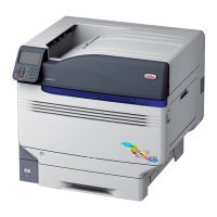
If moving the printer or replacing consumables
or maintenance units, or setting paper in the
tray, check the following points to prevent the
printer from toppling.
Do not press the front cover when the printer
font cover is open.
Do not press on the cassette from above when
the cassette is pulled out.
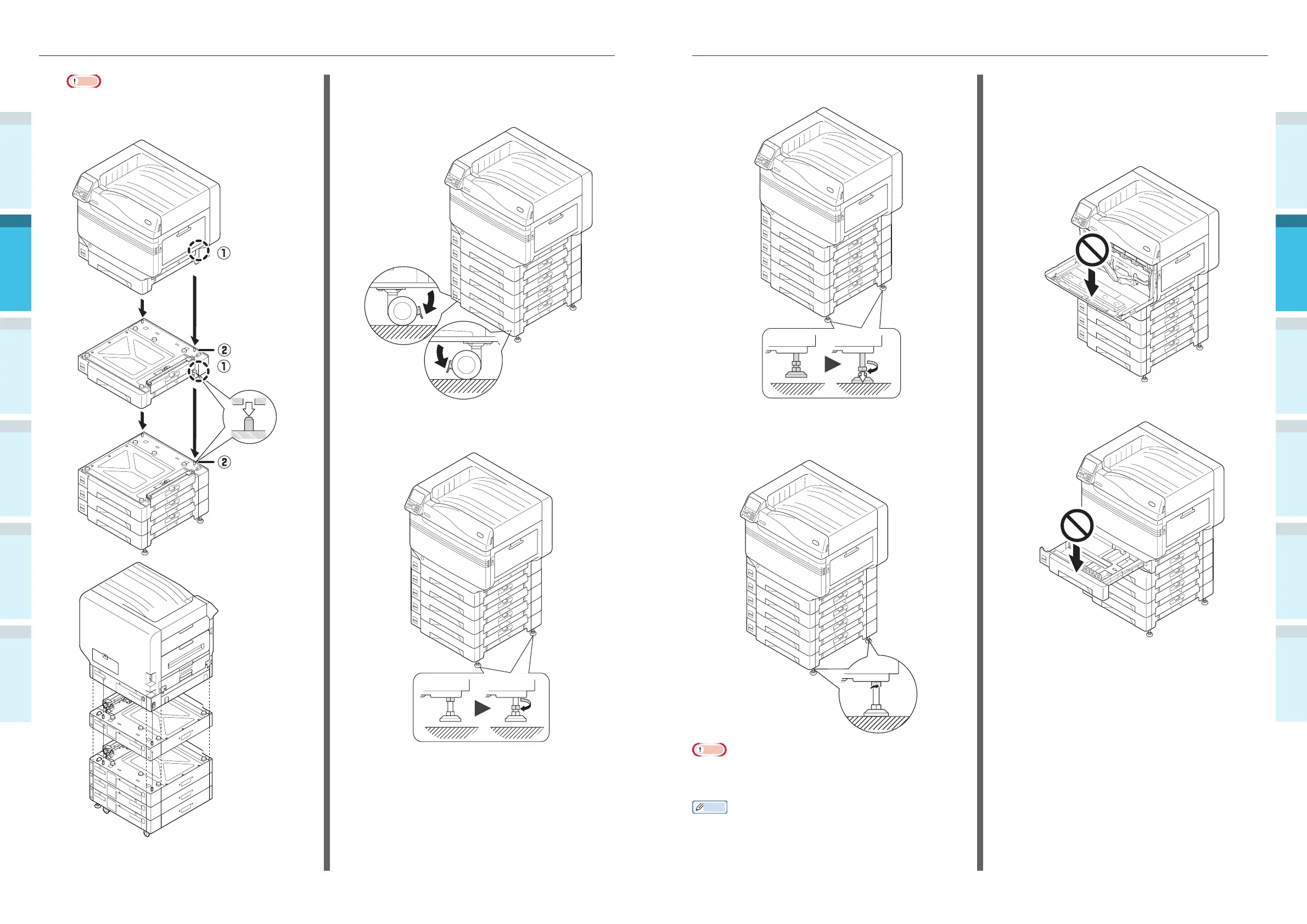
Note
�
If using the expansion tray unit and large-capacity
expansion tray unit, fi rst mount the expansion tray
unit to the large-capacity expansion tray unit, and then
mount the main printer unit to the expansion tray unit.
Printer
base hole
Protrusion
Protrusion
�
For the expansion tray unit and large-capacity expansion tray
unit with casters, adjust the caster locks (x2) and feet (x2).
3
Push down the lock levers on the
casters (x2) at the front of the device
to lock the casters.
4
Loosen the nuts (x2) at the top of the
feet on the right of the device.