21
L
R
L
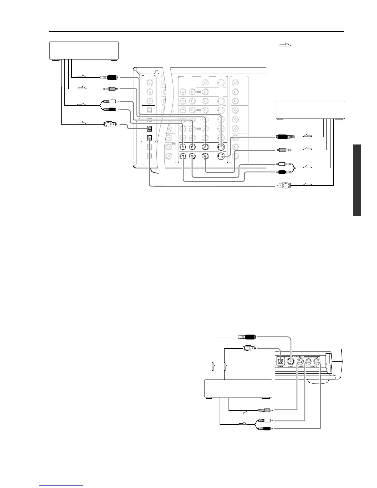
Connecting to Audio/Video equipment
S Video output
Digital output
(optical)
10. Video camera/ Video game
(VIDEO 5 INPUT)
Video output
Analog output
8, 9. Connecting a satellite tuner, television, or settop box
(VIDEO 3 or 4)
Using an RCA video cable, connect the video output jack
(composite) of the device to the VIDEO 3 (or 4) VIDEO IN jack of
the DTC-9.4. Or if the device has an S video output jack, connect it
to the VIDEO 3 (or 4) S VIDEO IN jack of the DTC-9.4 using an S
video cable. Or if the device has component video outputs, connect
them to one of the banks of COMPONENT VIDEO INPUT jacks on
the DTC-9.4.
The default setting for the VIDEO 3 and VIDEO 4 video inputs
are set to “VIDEO” (VIDEO IN or S VIDEO IN).
If you connect the device to video jacks other than the VIDEO IN or
S VIDEO IN jacks, change the setting for “b.Component Video” at
the “2-3.Video Setup sub-menu” to appropriate value (see page 59).
Using an RCA audio cable, connect the audio output jack of the
device to the VIDEO 3 (or 4) AUDIO IN jacks of the DTC-9.4.
Make sure that you properly connect the left channel to the L jack
and the right channel to the R jack.
If the device has a digital output, connect it to either the DIGITAL
INPUT COAX jack or DIGITAL INPUT OPT jack of the DTC-9.4
depending on the type of connector on the device.
With the initial settings of the DTC-9.4, the VIDEO 3 input source is
set for digital input at the OPT 3 jack, and the VIDEO 4 input
source is set for digital input at the OPT 4 jack.
If the digital connection is made at a different jack, this must be
changed at Setup Menu → Input Setup → Digital Setup (see page
57).
: Signal flow
8. Settop box, video camera
(VIDEO 3)
S Video output
Video output
Analog audio
output
Digital audio output (optical)
9. Satellite tuner or television
(VIDEO 4)
S Video output
Video output
Analog audio
output
Digital audio output
(optical)
10. Connecting video camera, etc. (VIDEO 5 INPUT)
Using an RCA video cable, connect the video output jack
(composite) of the device to the VIDEO 5 VIDEO jack of the DTC-
9.4. Or if the device has an S video output jack, connect it to the
VIDEO 5 S VIDEO jack of the DTC-9.4 using an S video cable.
Using an RCA audio cable, connect the audio output jack of the
device to the VIDEO 5 AUDIO jacks of the DTC-9.4. Make sure that
you properly connect the left channel to the L jack and the right
channel to the R jack.
If the device has an optical digital output, connect it to the VIDEO 5
DIGITAL jack of the DTC-9.4.
The VIDEO 5 digital input is fixed to the OPTICAL input on the
front panel.
R (red)
L (white)
R (red)
L (white)
Front panel
 Loading...