INPUT
FRONT
R
L
DIGITAL
INPUT
OPT
2
1
2
1
3
COAX
CENTER
R
L
R
L
R
L
87654321
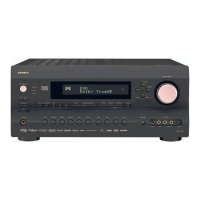
1. Front left speaker
2. Front right speaker
3. Subwoofer
4. Surround back left/Zone 2
left speaker
5. Surround back right/Zone 2
right speaker
6. Surround left speaker
7. Surround right speaker
8. Center speaker
Front
Surround
Center
Surround
back
Subwoofer
to White
to Red
to Purple
to Brown
to Tan
to Blue
to Green
to Gray
Power amplifier
Connecting to devices with analog multi channel
output
Connect a DVD player, MPEG decoder, or other component that has
a multi channel port for 5.1 channel or 7.1 channel output.
Connecting to an external device with 12V
TRIGGER terminal
These terminals are provided so that you can use the operation of the
DTC-9.4 control the operation of another externally connected
device. Connect the component to this 1/8-inch mini-jack terminal
and when the set input source is selected, the device will turn on. Set
the 12V TRIGGER terminal using the Setup menu: Input setup →
12V trigger (see page 60).
When the DTC-9.4 is in the ZONE 2 mode, the 12V TRIGGER
ZONE 2 terminal outputs at 12 V/100 mA.
The 12V TRIGGER OUT B (CONTROL LINK OUT) terminal on
the DTC-9.4 is for connecting to the Integra DTA-9.4 power
amplifier.
When the DTC-9.4 is connected to the DTA-9.4, the DTA-9.4 can be
turned on or entered into standby state in conjunction with the “on”
or “standby” states of the DTC-9.4.
The Dimmer function of the DTA-9.4 for the On indicator brightness
will also work in conjunction with the Dimmer function of the DTC-
9.4 for the display brightness. Use the mini-plug cable supplied with
the DTA-9.4 for connecting to the 12V TRIGGER IN terminal on
the DTA-9.4.
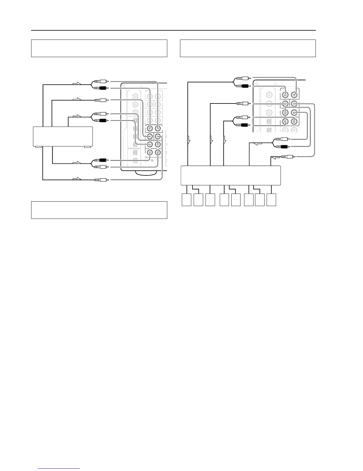
Connecting auxiliary power amplifiers with RCA
type connector
Connect your power amplifier to the PRE OUT jacks on the DTC-9.4.
Note:
For connections when you enjoy music and video in the remote room
(Zone 2), see page 25.