Datasheet, Volume 1 27
Interfaces
2.2 PCI Express* Interface
This section describes the PCI Express interface capabilities of the processor. See the
PCI Express Base Specification for details of PCI Express.
The processor has one PCI Express controller that can support one external x16 PCI
Express Graphics Device. The primary PCI Express Graphics port is referred to as
PEG 0.
2.2.1 PCI Express* Architecture
Compatibility with the PCI addressing model is maintained to ensure that all existing
applications and drivers operate unchanged.
The PCI Express configuration uses standard mechanisms as defined in the PCI
Plug-and-Play specification. The initial recovered clock speed of 1.25 GHz results in
2.5 Gb/s/direction that provides a 250 MB/s communications channel in each direction
(500 MB/s total). That is close to twice the data rate of classic PCI. The fact that
8b/10b encoding is used accounts for the 250 MB/s where quick calculations would
imply 300 MB/s. The external graphics ports support Gen2 speed as well. At 5.0 GT/s,
Gen 2 operation results in twice as much bandwidth per lane as compared to Gen 1
operation. When operating with two PCIe controllers, each controller can be operating
at either 2.5 GT/s or 5.0 GT/s.
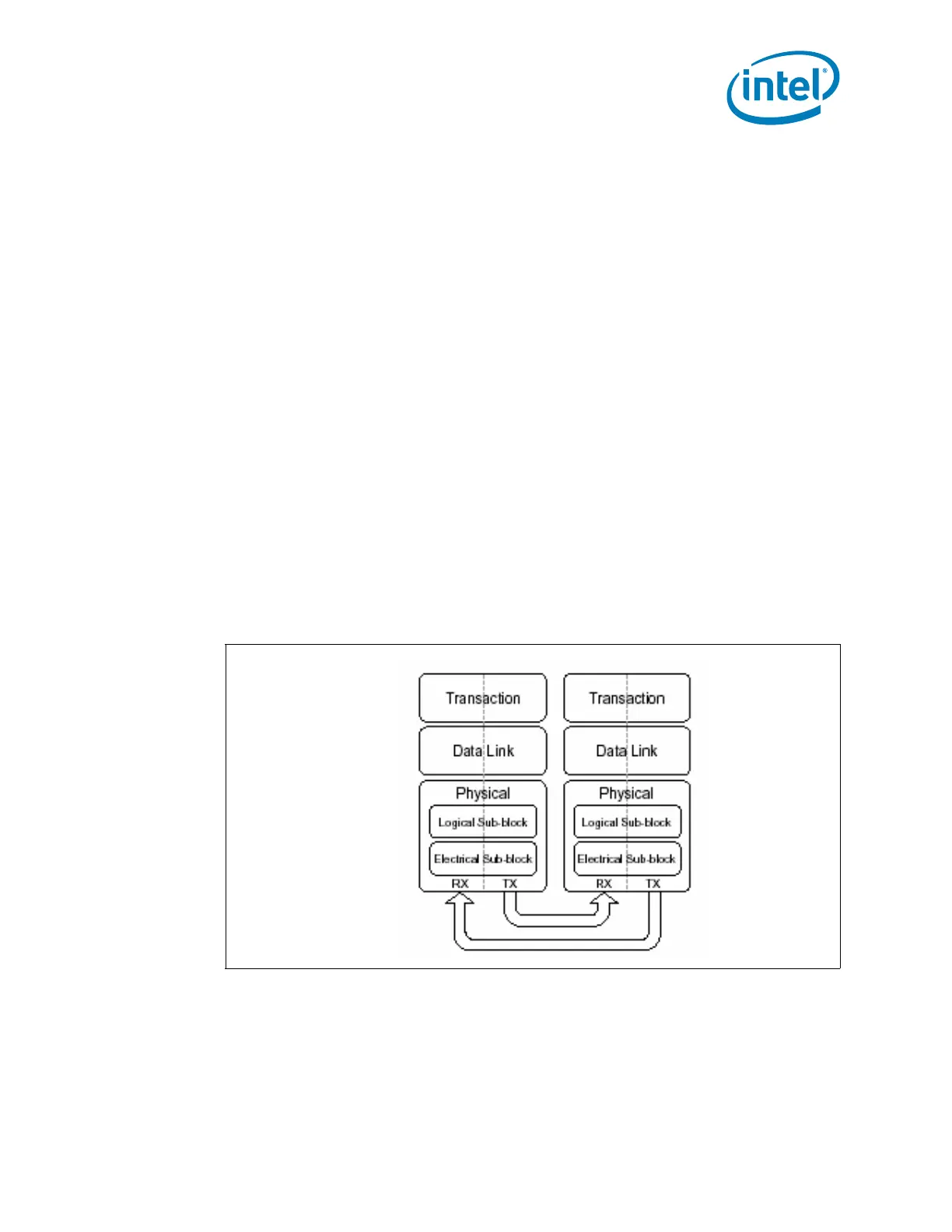
The PCI Express architecture is specified in three layers—Transaction Layer, Data Link
Layer, and Physical Layer. The partitioning in the component is not necessarily along
these same boundaries. Refer to Figure 2-2 for the PCI Express Layering Diagram.
PCI Express uses packets to communicate information between components. Packets
are formed in the Transaction and Data Link Layers to carry the information from the
transmitting component to the receiving component. As the transmitted packets flow
through the other layers, they are extended with additional information necessary to
handle packets at those layers. At the receiving side, the reverse process occurs and
Figure 2-2. PCI Express* Layering Diagram

 Loading...


