Chapter
3.
Instruction
Set
RST
3-54
Example:
[_O
___
O
___
O
__
O
_________
l~
Cycles:
States:
Flags:
1
4
CY
only
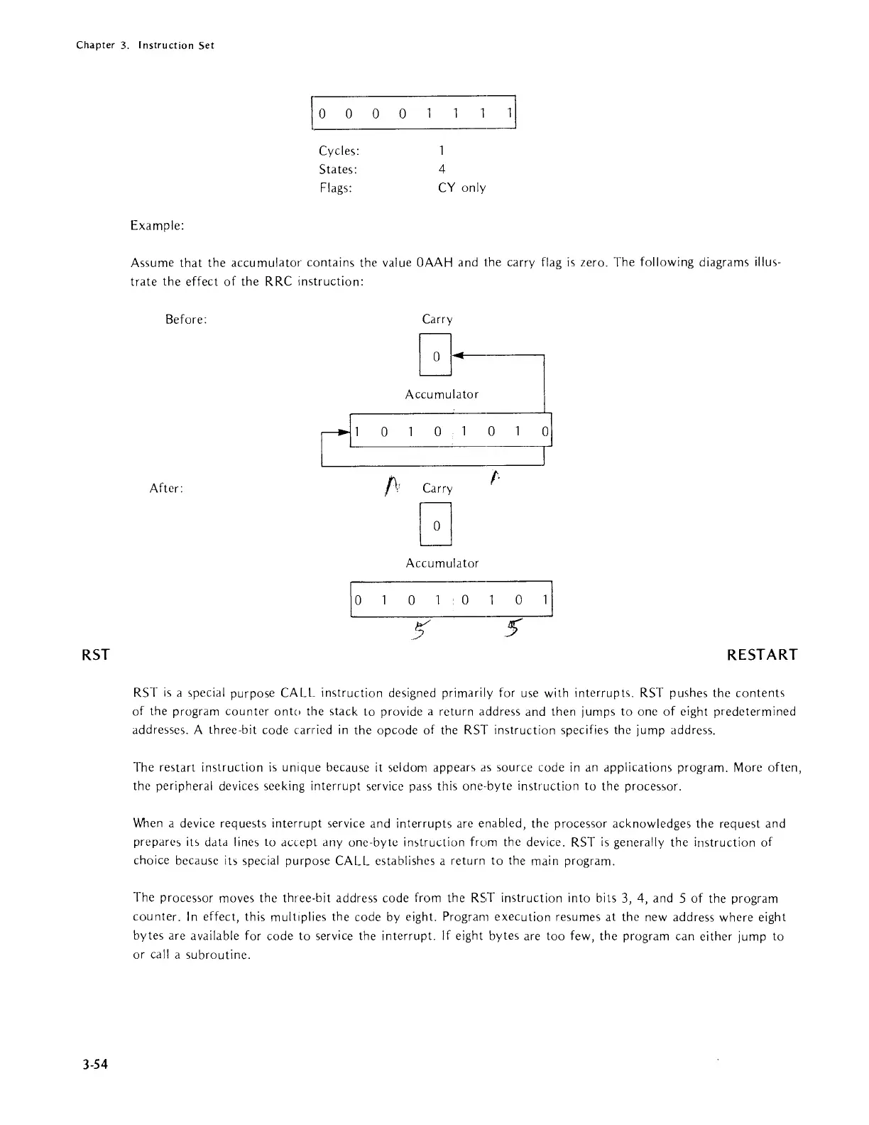
Assume
that
the accumulator contains the value
OAAH
and the carry flag
is
zero. The following diagrams illus-
trate
the
effect
of
the RRC instruction:
Before:
Carry
G.-
Accumulator
r
'
0
0
0
After:
f\r
Carry
r
G
Accumulator
\~O
______
O
_____
O
__
~
5' 5'
RESTART
RST
is
a ,pecial purpose CALL instruction designed primarily for use with interrupts. RST pushes the
contents
of
the program
counter
ontc) the stack to provide a return address and then jumps
to
one
of
eight predetermined
addresses. A three-bit code
can-ied
in
the opcode
of
the RST instruction specifies the jump address.
The restart instruction
is
unique because
it
seldom appears
as
source code
in
an
applications program. More often,
the
peripheral devices seeking interrupt service pass this
one·byte
instruction to the proces<,or.
When
a device reque,ts
interrupt
service and interrupts are enabled, the processor acknowledges the request and
prepare,
it>
data line, to accept
anyone-byte
in,truction
frum the device. RST
is
generally the instruction
of
choice because its special purpose CALL establishes a return
to
the main program.
The
proces,or moves the three-bit address code from
the
RST instruction into bits 3, 4, and 5
of
the program
counter.
In
effect, this multiplies the code
by
eight. Program execution resumes
at
the new address where eight
bytes are
available for code to service the interrupt. If eight bytes are too few, the program can either jump to
or
call a subroutine.