Chapter
3.
Instruction
Set
3-60
v
L{
RSn.S
MASK
RST6.S
MASK
RSTS.S
MASK
{
o
= available
1
= masked
flf
0, bits 0
..
2 ignored
Mask
Set Enable
\If
1, mask
is
set
RESET
RSn.S:
If
1,
RSn.S
flip flop
is
reset
OFF
ignored
If 1, bit 7
is
ou
tput
to Serial
Output
Data Latch
Serial
Output
Data: ignored if bit 6 = 0
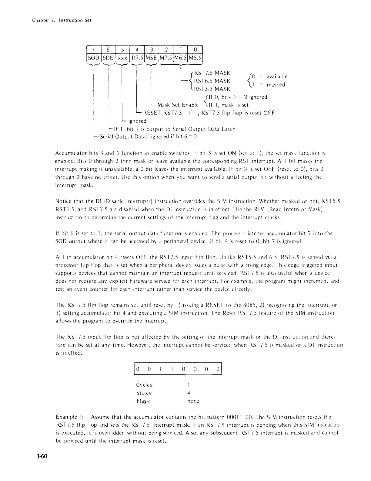
Accumulator bits 3 and 6 fUllction as enable switches.
If
bit 3
is
set
ON
(set to 1), the set mask function
is
enabled. Bits 0 through 2 then mask or leave available the corresponding RST interrupt. A 1 bit masks the
interrupt
making it unavailable; a 0 bit leaves the
interrupt
available.
If
bit 3
is
set
OFF
(reset to 0), bits 0
through 2 have no effect.
Usc
this
option
when you want
L)
send a serial
output
bit
without
affecting the
interrupt
mask.
Notice
that
the
01
(Disable Interrupts) instruction overrides the
SI
M instruction. Whether masked or not, RSTS.S,
RST6.S, and RST7.S are disdblcd when the
01
instruction
i'>
in
effect.
Use
the
RIM
(Read Interrupt Ma,k)
instruction to determine the
current
setting'>
of
the interrupt flag and the
interrupt
mdsks.
If
bit 6
is
,et
to 1, the serial
output
datd function
is
enabled. The processor
Idtche'>
dccumuldtor bit 7 into the
SOD
output
where it can
be
accessed
by
a peripheral device.
If
bit 6
is
re,et
to 0, bit 7
is
ignored.
A 1
in
accumulator bit 4 res.?ts
OFF
the RST7.S input flip flop. Unlike RSTS.S dnd 6.S, RST7.S
is
'>ensed
Vld
a
processor flip flop
that
is
set when a peripheral device issues d pulse with a rising edge. This edge triggered
input
supports
devices
that
cannot
maintain
an
interrupt
request until serviced. RST7.S
is
also
u'>eful
when a device
does
not
require any explicit hardware service for each interrupt. For example, the program might increment and
test
an
event cou nter for each interrupt rather than service the device directly.
The RST7.S flip flop
remains set
l.Intil
reset
by
1)
issuing a RESET to
the
808S,
2)
recogni/ing the interrupt, or
3)
setting
accumulator
bit 4 and executing a
SIM
instruction. The Reset RST7.S feature
of
the
SIM
instruction
allows
the program to override the interrupt.
The RST7.S
input
flip flop
is
not affected
by
the setting of the interrupt mask or the
01
instruction and there·
fore can
be
set
at
any time. However, the
interrupt
cannot
be
,erviced when RST7.S
is
masked or d
01
instruction
is
in
effect.
10
0
Cycles:
States:
Flags:
o 0
c~
1
4
none
Example
1:
Assume
that
the accumulator contains the bit pattern
00011100.
The
SIM
instruction resets the
RST7.S flip flop and sets the RST7.S
interrupt
mask.
If
an RST7.S
interrupt
i'>
pending when this
SI
M instructio
is
executed, it
is
overridden
without
being serviced. Also, anv subsequent RST7.S
interrupt
is
masked and
cannot
be
serviced until the
interrupt
mask
is
reset.