RZ
Chapter
3.
Instruction
Set
8085
NOTE
The
8085
processor includes
four
hardware inputs
that
generate intrrnal RST
instructions. Rather than send a RST instruction, the interrupting device need
only apply a signal
to
the RST5.5, RST6.5, RST7.S, or TRAP input pin.
The processor then generates
an
internal RST instruction. The execution
depends on the
input
INPUT
RESTART
NAME
ADDRESS
TRAP
24H
RST5.5
2CH
RST6.5
34H
RST7
.5
3CH
Notice
that
these addre'>ses are within the same portion
of
rr,ernory
u'>ed
by
the RST instruction, and therefore
allow only four
byte'>
- enough for a call or jump and a return for the interrupt service routine.
If included
in
the program code, the RST instruction
ha'>
the following format:
Opcode Operand
RST code
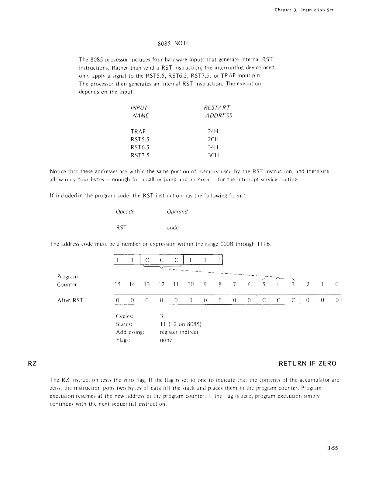
The
addre5'>
code must
be
a number or
expre,>,>ion
within the range
OOOB
through
111
B.
1=:3
Progr am
~------.
Cou nter
15 14
13
12
11
10
9
8
7
(j
5 4 3
2
After
RST
Eo
0
0
0 0 0
0
0 0
C C
C
0
0
Cycles:
3
Std tes:
11
(12 on 8085)
Addre'>',ing:
register indirect
Flag';: none
0
01
RETURN
IF
ZERO
The RZ
imtruction
test,
the zero flag. If the flag
is
set to one to indicate
that
the
contents
of
the accumulator are
zero, the instruction pops two bytes of data
off
the stack and places them
in
the program counter. Program
execution resumes at the new address
in
the program counter. If the
flag
is
zero, program execution simply
continues with the next sequential instruction.
3-55