Chapter
1.
Assembly
Language
and
Processors
can
be
assigned within those addresses. However, the relocation feature
of
this a'isembler allows you to code a
program without concern for the ultimate placement
of
data and instructions; these program elements can be
repositioned after the program has been tested and after the system's memory layout
is
final. The relocation
feature
is
fully explained
in
Chapter 4
of
this manual.
Program Counter
1-6
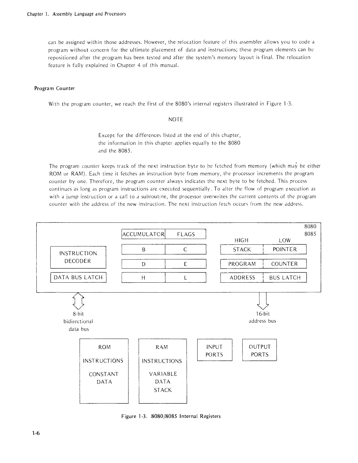
With
the program counter,
we
reach the first
of
the 8080's internal registers illustrated
in
Figure 1·3.
NOTE
Except for the difference<, listed at the end
of
this chapter,
the information
in
this chapter applies equally to the 8080
dnd
the 8085.
The program counter keeps track of the next instruction byte to be fetched from memory (which may
be
either
ROM
or RAM). Each time
it
fetches an instruction bytc from memory,
tlcc
processor increments thc program
counter
by
one. Therefore, the program counter always indicates the next byte to
be
fetched. This proccss
continues
as
long
a'>
program instructions are executed sequentially. To alter the flow
of
program execution
as
with a jump instruction or a call to d
,>ubrouti
ne, the processor overwrites the current contents of the program
counter with the addrcss
of
thc new instruction. The next in<,truction fetch
occur>;
from the new address.
IACCUMULATORI
FLAGS
INSTRUCTION
DECODER
DATA
BUS
LATCH
8·bit
bidirectional
data bus
ROM
INSTRUCTIONS
CONSTANT
DATA
B
D
H
RAM
INSTRUCTIONS
VARIABLE
DiHA
STACK
C
E
L
HIGH
LOW
[
STACK
POINTER
[PROGRAM
COUNTER
[ ADDRESS
BUS
LATCH
INPUT
PORTS
16·bit
address bus
OUTPUT
PORTS
Figure 1-3.
8080/8085
I nternal Registers
8080
8085