Chapter
1.
Assembly
language
and Processors
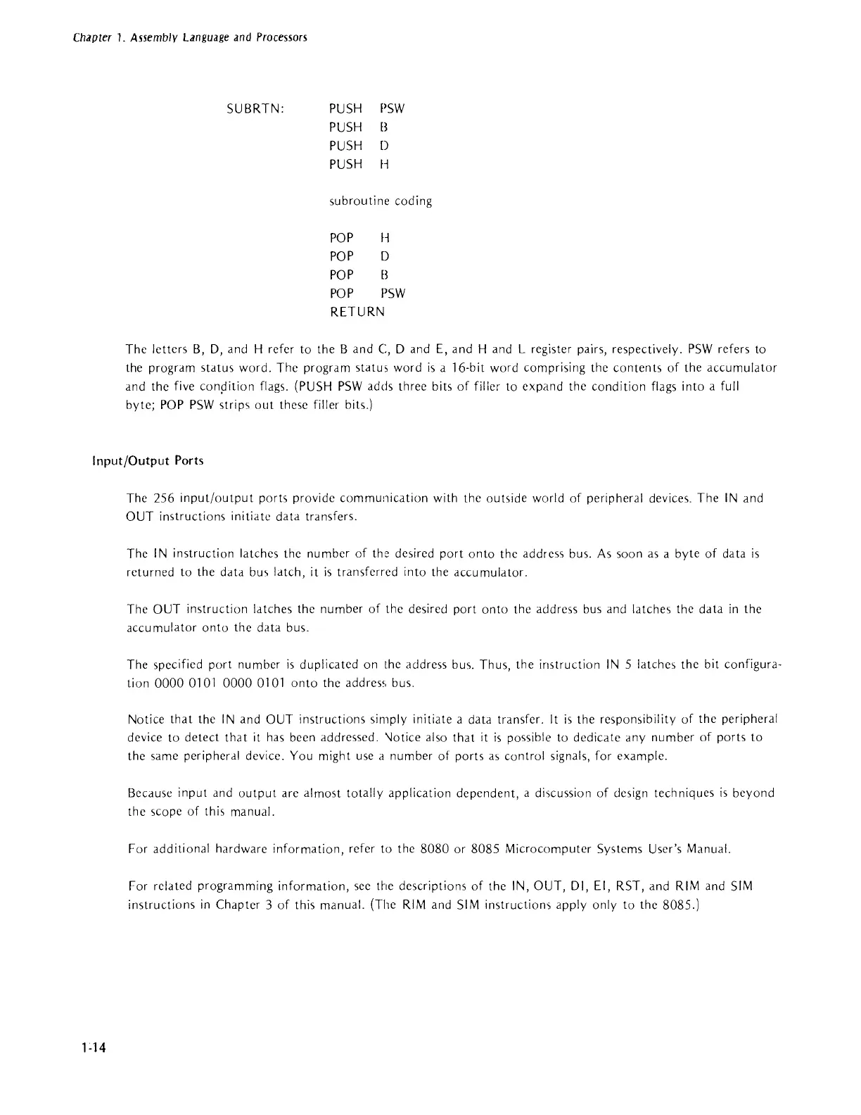
SUBRTN: PUSH
PUSH
PUSH
PSW
B
[)
PUSH H
subroutine coding
POP
H
POP
[)
POP B
POP
PSW
RETURN
The letters
B,
D,
and H refer to the
Band
C, D and E, and
Hand
L register pairs, respectively.
PSW
refers to
the program status word. The program status word
is
a 16-bit word comprising the
contents
of
the
accumulator
and the five conpition flags. (PUSH
PSW
adds three bits
of
filler to expand the condition flags into a full
byte;
POP
PSW
strips
out
these filler bits.)
Input/Output
Ports
1-14
The 256
input/output
ports provide communication with the outside world
of
peripheral devices. The
IN
and
OUT instructions initiate data transfers.
The
IN
instruction latches the number
of
the de,ired
port
onto
the address bus.
As
soon
as
a byte
of
data
is
returned to the data
bu,>
latch, it
is
transferred into the accumulator.
The
OUT instruction latches the number
of
the desired port
onto
the address bus and latches the data
in
the
accumulator
onto
the data bus.
The specified port number
is
duplicated on the address bus. Thus,
the
instruction
IN
5 latches the bit configura-
tion
00000101
00000101
onto
the add res', bus.
Notice
that
the
IN
and OUT instructions simply initiate a data transfer.
It
is
the responsibility
of
the peripheral
device to
detect
tha
tit
has been addressed. \Jo tice
al
so
that
it
is
possible to ded ica te any
nu
m ber
of
ports
to
the same peripheral device. You might use a number of ports
a,
control signals, for example.
Because input and
output
are almost totally application dependent, a discussion
of
design techniques
is
beyond
the scope
of
this manual.
For additional hardware information, refer to the
8080
or 8085 Microcomputer Systems User's Manual.
For related programming information, see the descriptions
of
the IN, OUT, DI, EI, RST, and
RIM
and
SIM
instructions
in
Chapter 3
of
this manual. (The
RIM
and
SIM
instructiom
apply only to the 8085.)