OUT
Chapter
3.
Instruction
Set
Example:
AND
1010 1010
0000 1111
0000 1010
OR
1010 1010
00001111
1010
1111
EXCLUSIVE OR
1010 1010
0000 1111
1010 0101
Sec the description
of
the ORA instruction for an example of the use of the inclusive OR. The following
examples show
a number
of
methods for defining immediate data
in
the ORI instruction.
All
of
the examples
generate the bit pattern for the
ASCII character
A.
ORI
OR!
ORI
OR!
OR!
OR!
010000018
'A'
41H
101Q
65
5+30*2
OUTPUT
TO
PORT
The OUT instruction places the contents
of
the accumulator on the eight-bit data bus and the number
of
the
selected
port
on the sixteen-bit address bus. Since the number
of
ports ranges from 0 through 255, the port
number
is
duplicated on the address bus.
It
is
the responsibility
of
external logic to decode the port number and to accept the
output
data.
NOTE
Because a discussion of
input/output
structures
is
beyond the scope
of
this manual, this description
is
restricted to the exact function
of
the
OUT instruction.
Input/output
structures are described
in
the
8080
or
8085 Microcomputer Systems
User's Manual.
Opcode
Operand
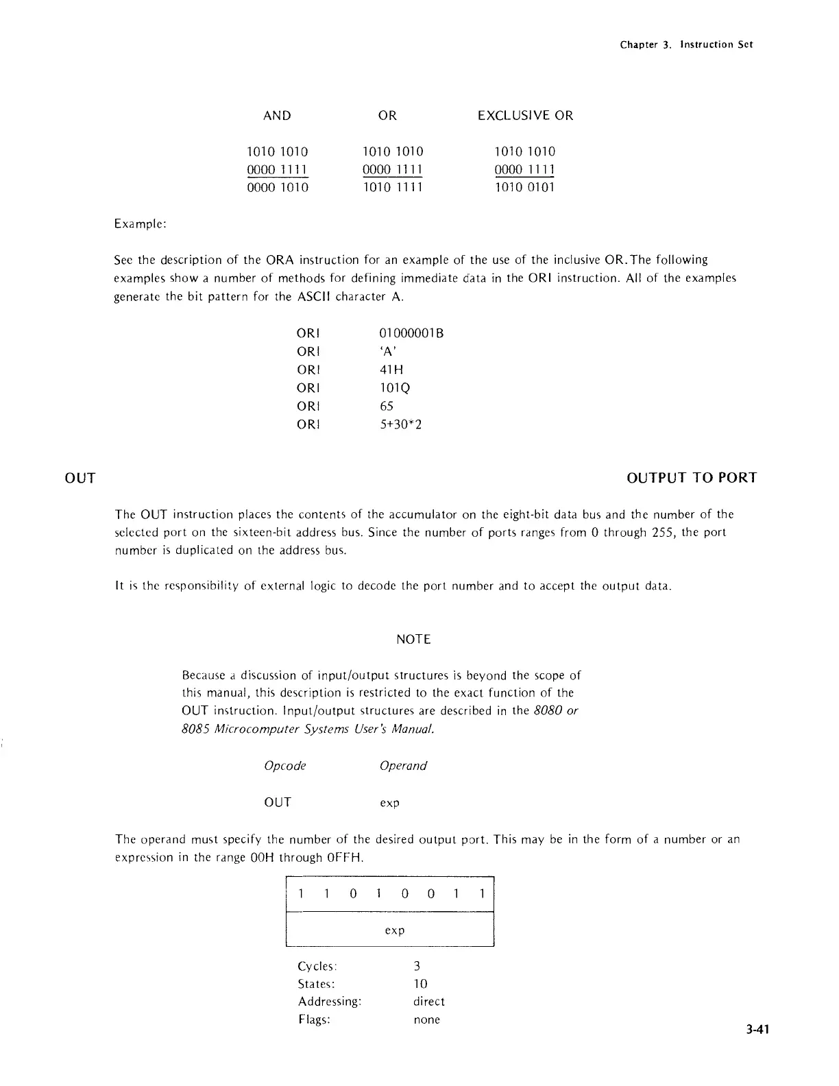
OUT exp
The operand
must specify the number
of
the desired
output
port. This may be
in
the form
of
a number or
an
expre<,sion
in
the rdnge
OOH
through OFFH.
[_0
,-xpo
° 1
j.
Cycles:
States:
Addressing:
Flags:
3
10
direct
none
3-41