Intel Desktop Board D850MD/D850MV Technical Product Specification
62
Table 34. Main Power Connector
Pin Signal Name Pin Signal Name
1 +3.3 V 11 +3.3 V
2 +3.3 V 12 -12 V
3 Ground 13 Ground
4 +5 V 14 PS_ON# (power supply remote on/off)
5 Ground 15 Ground
6 +5 V 16 Ground
7 Ground 17 Ground
8 PWRGD (Power Good) 18 TP_PWRCONN_18
9 +5 V (Standby) 19 +5 V
10 +12 V 20 +5 V
Table 35. Optional Auxiliary Power Connector
(Required for AGP Pro Only)
Pin Signal Name
1 Ground
2 Ground
3 Ground
4 +3.3 V
5 +3.3 V
6 +5 V
Table 36. Fan 2 Connector
Pin Signal Name
1 FAN_CNTRL
2 +12 V
3 Tachometer (FAN_2)
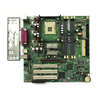
2.8.2.4 Add-in Board and Peripheral Interface Connectors
Figure 15 and Figure 16 show the locations of the add-in board connectors and peripheral
connectors for the D850MD and D850MV boards respectively. Note the following considerations
for the PCI bus connectors:
• All of the PCI bus connectors are bus-master capable.
• PCI bus connector 2 has SMBus signals routed to it, which enables PCI bus add-in boards with
SMBus support to access sensor data on the board. The specific SMBus signals are as follows:
The SMBus clock line is connected to pin A40
The SMBus data line is connected to pin A41