Intel Desktop Board D850MD/D850MV Technical Product Specification
72
2.8.3.2 Front Panel Connector
This section describes the functions of the front panel connector. Table 46 lists the signal names
of the front panel connector.
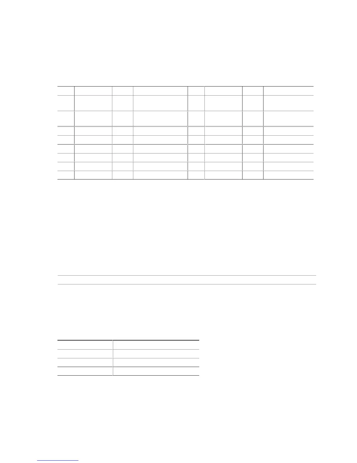
Table 46. Front Panel Connector
Pin Signal In/Out Description Pin Signal In/Out Description
1 HD_PWR Out Hard disk LED pull-
up (330 Ω) to +5 V
2 HDR_BLNK_
GRN
Out Front panel green
LED
3 HAD# Out Hard disk active LED 4 HDR_BLNK_
YEL
Out Front panel yellow
LED
5 Ground Ground 6 FPBUT_IN In Power switch
7 FP_RESET# In Reset switch 8 Ground Ground
9 +5 V Out Reserved 10 N/C
11 Reserved In Reserved 12 Ground Ground
13 Ground Ground 14 (pin removed) Not connected
15 Reserved Out Reserved 16 +5 V Out Power
2.8.3.2.1 Reset Switch Connector
Pins 5 and 7 can be connected to a momentary (SPST type) switch that is normally open. When
the switch is closed, the D850MD/D850MV boards reset and run the POST.
2.8.3.2.2 Hard Drive Activity LED Connector
Pins 1 and 3 can be connected to an LED to provide a visual indicator that data is being read from
or written to a hard drive. For the LED to function properly, an IDE drive must be connected to
the onboard IDE interface. The LED will also show activity for devices connected to the SCSI
hard drive activity LED connector.
For information about Refer to
The SCSI hard drive activity LED connector Section 1.8.3.2, page 30
2.8.3.2.3 Power/Sleep/Message-Waiting LED Connector
Pins 2 and 4 can be connected to a one- or two-color LED. Table 47 shows the possible states for
a one-color LED. Table 48 shows the possible states for a two-color LED.
Table 47. States for a One-Color Power LED
LED State Description
Off Power off/sleeping
Steady Green Running
Blinking Green Running/message waiting