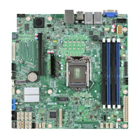
List of Tables Intel® Server Board S3420GP TPS
Revision 2.4
Intel order number E65697-010
x
List of Tables
Table 1. Intel
®
Server Board S3420GP Feature Set ...................................................................... 2
Table 2. Major Board Components ................................................................................................ 7
Table 3. Standard Platform DIMM Nomenclature ........................................................................ 21
Table 4. Memory Configuration Table .......................................................................................... 22
Table 5. UDIMM memory configuration rule ................................................................................ 23
Table 6. UDIMM Maximum configuration ..................................................................................... 23
Table 7. RDIMM memory configuration rule ................................................................................ 24
Table 8. RDIMM Maximum configuration ..................................................................................... 24
Table 9. Optional RMM3 Advanced Management Board Features ............................................. 30
Table 10. Serial B Header (J1B1) Pin-out .................................................................................... 30
Table 11. Video Modes ................................................................................................................. 31
Table 12. Dual Video Modes ........................................................................................................ 32
Table 13. Setup Utility — Hardware Monitor Screen Fields ........................................................ 41
Table 14. Setup Utility — Hardware Monitor Screen Fields ........................................................ 43
Table 15. Setup Utility — Voltage and Temperature Status Fields ............................................. 44
Table 16. BIOS Setup Page Layout ............................................................................................. 48
Table 17. BIOS Setup: Keyboard Command Bar ........................................................................ 49
Table 18. Setup Utility – Main Screen Fields ............................................................................... 51
Table 19. Setup Utility – Advanced Screen Display Fields .......................................................... 53
Table 20. Setup Utility – Processor Configuration Screen Fields ................................................ 54
Table 21. Setup Utility – Memory Configuration Screen Fields ................................................... 56
Table 22. Setup Utility – Mass Storage Controller Configuration Screen Fields ......................... 58
Table 23. Setup Utility – Serial Ports Configuration Screen Fields ............................................. 59
Table 24. Setup Utility – USB Controller Configuration Screen Fields ........................................ 61
Table 25. Setup Utility – PCI Configuration Screen Fields .......................................................... 62
Table 26. Setup Utility – System Acoustic and Performance Configuration Screen Fields ........ 63
Table 27. Setup Utility – Security Configuration Screen Fields ................................................... 64
Table 28. Setup Utility – Server Management Configuration Screen Fields ............................... 66
Table 29. Setup Utility – Console Redirection Configuration Fields ............................................ 68
Table 30. Setup Utility – Server Management System Information Fields .................................. 69
Table 31. Setup Utility – Boot Options Screen Fields .................................................................. 70
Table 32. Setup Utility – Delete Boot Option Fields ..................................................................... 72
Table 33. Setup Utility — Hard Disk Order Fields ........................................................................ 72
Table 34. Setup Utility – CDROM Order Fields............................................................................ 73
Table 35. Setup Utility — Floppy Order Fields ............................................................................. 73
Table 36. Setup Utility – Network Device Order Fields ................................................................ 74
Table 37. Setup Utility – Boot Manager Screen Fields ................................................................ 74
Table 38. Board Connector Matrix ............................................................................................... 76
Table 39. Baseboard Power Connector Pin-out (J9A1) ............................................................... 77

 Loading...
