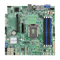
Intel® Server Board S3420GP TPS List of Tables
Revision 2.4
Intel order number E65697-010
xi
Table 40. SSI Processor Power Connector Pin-out (J9C1) ......................................................... 77
Table 41. Intel
®
RMM3 Connector Pin-out (J2C1) ....................................................................... 78
Table 42. LPC/IPMB Header Pin-out (J1H2) ............................................................................... 78
Table 43. HSBP Header Pin-out (J1J1) ....................................................................................... 78
Table 44. SGPIO Header Pin-out (J1J3) ...................................................................................... 79
Table 45. Front Panel SSI Standard 24-pin Connector Pin-out (J1C1) ....................................... 79
Table 46. System Status LED Indicator States ............................................................................ 80
Table 47. VGA Connector Pin-out (J7A1) .................................................................................... 81
Table 48. RJ-45 10/100/1000 NIC Connector Pin-out (J5A1) ..................................................... 82
Table 49. RJ-45 10/100/1000 NIC Connector Pin-out (J6A1) ..................................................... 82
Table 50. SATA Connector Pin-out (J1H4, J1H1, J1G1, J1H3, J1G3, J1F4) ............................. 83
Table 51. 50-pin PCI Express* Connector Pin-out (J2H1) ........................................................... 83
Table 52. External Serial A Port Pin-out (J8A1) ........................................................................... 84
Table 53. Internal 9-pin Serial B Header Pin-out (J1B2) ............................................................. 84
Table 54. Internal USB Connector Pin-out ( J1E1, J1D1) ........................................................... 84
Table 55. Pin-out of Internal USB Connector for Floppy ( J1J2) ................................................. 85
Table 56. Pin-out of Internal USB Connector for low-profile Intel
®
Z-U130 Value Solid State
Drive (J3F2) ............................................................................................................................ 85
Table 57. Pin-out of adaptive riser slot/PCI Express slot 6 .......................................................... 85
Table 58. SSI 4-pin Fan Header Pin-out (J6D1, J1J4, J6J2, J7J1, J6B1) .................................. 90
Table 59. Server Board Jumpers (J1F1, J1F2, J1F3, J1F5, J1A2) ............................................. 91
Table 60. Front Panel Status LED Behavior Summary................................................................ 95
Table 61. POST Code Diagnostic LED Location ......................................................................... 96
Table 62. Server Board Design Specifications............................................................................. 97
Table 63. Intel
®
Xeon
®
Processor TDP Guidelines ...................................................................... 98
Table 64. 350-W Load Ratings ..................................................................................................... 99
Table 65. Voltage Regulation Limits ........................................................................................... 100
Table 66. Transient Load Requirements .................................................................................... 100
Table 67. Capacitve Loading Conditions ................................................................................... 100
Table 68. Ripple and Noise ........................................................................................................ 101
Table 69. Output Voltage Timing ................................................................................................ 101
Table 70. Turn On/Off Timing ..................................................................................................... 102
Table 71. Over-Current Protection (OCP) .................................................................................. 104
Table 72. Over-voltage Protection (OVP) Limits ........................................................................ 104
Table 73. Integrated BMC Core Sensors ................................................................................... 115
Table 74. POST Progress Code LED Example ......................................................................... 119
Table 75. Diagnostic LED POST Code Decoder ....................................................................... 120
Table 76. POST Error Messages and Handling ......................................................................... 123
Table 77. POST Error Beep Codes ............................................................................................ 127

 Loading...
