D-0120794-C – 2019/11
Orion Rotary Chair Installation Instructions Page 31
5 Computer configuration
The following connections to be made between computer and the other accessories including Orion AT/C
chair.
5.1 Isolation Transformer:
The isolation transformer input voltage is set from the factory to 115v for the Orion AT/C Chair. If it is
necessary to change the input voltage to 230v, remove the 115v (10A) fuses from the power entry and install
the 230v (5A) fuses and make sure to rotate the fuse holder so that 230v is showing through the window. To
do this, use the transformer manual and 230v (5A) fuses supplied with the transformer.
The output of the transformer is set to 115V from the factory and should never be changed.
The extra grounding cable is to be connected from Isolation transformer to an earth ground point. The
connecting procedure is explained in the pictures.
Power cables connect the isolation transformer to the computer, chair controller and patient monitor.
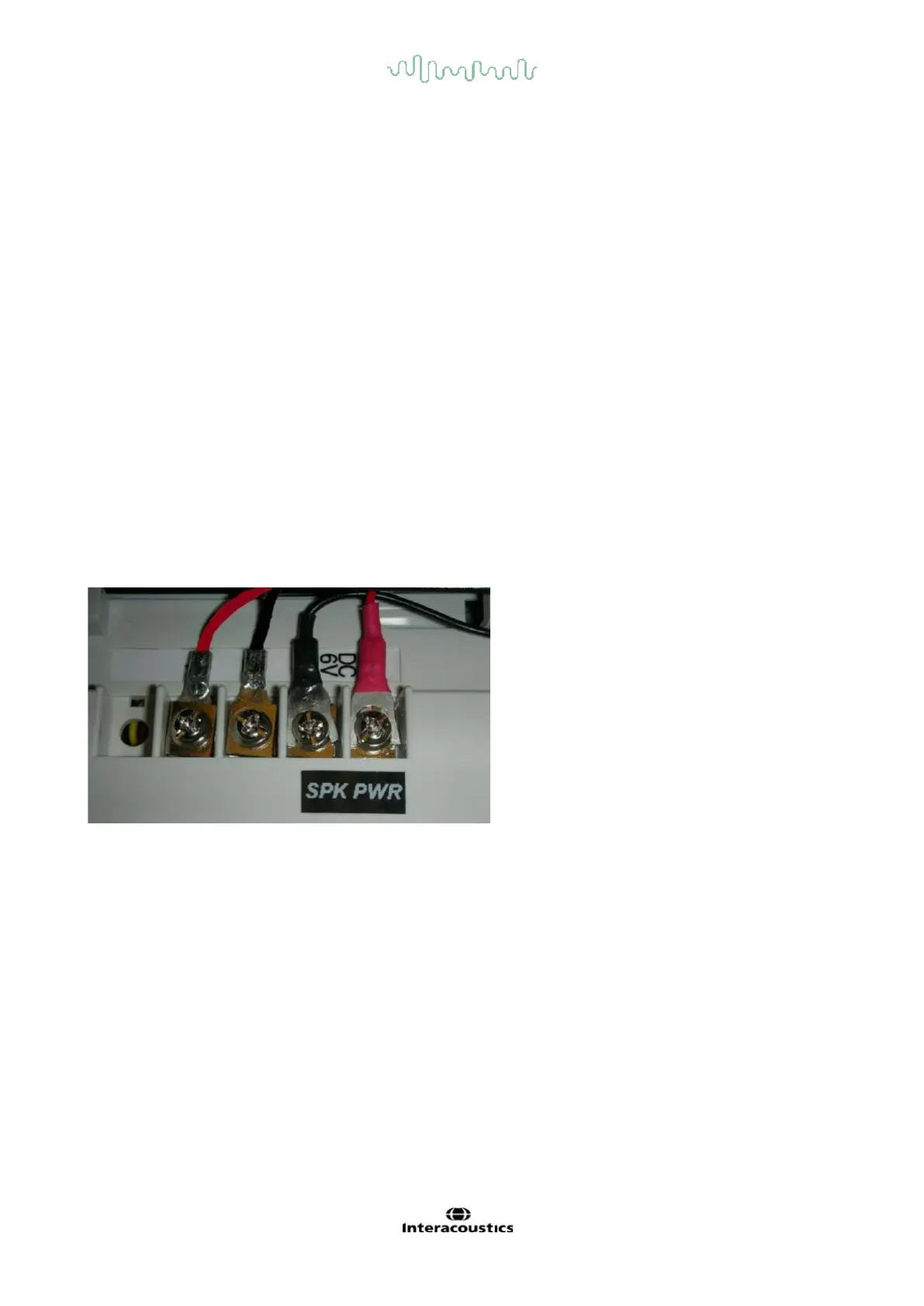
5.2 Intercom Speaker
The intercom has four screw connections on the back. Two screws are for the speaker wires (grey wires)
from the booth ceiling. The other two screws are from the dc power supply for the intercom. Press the right
button on the top of the intercom to talk to the patient, and release the button to listen to the patient.
Important: The intercom will not work unless the booth door is closed to prevent feedback whistle.
5.3 Installation of Booth Observation Camera and monitor
An infrared patient observation camera is attached to the inside of the chair booth next to the door to give the
operator visual feedback of the patient and provide an intercom between the operator and the patient. The
observation camera’s image is wirelessly transmitted to the observation monitor on the cart.
Pull the connecting wire for booth observation camera from the booth ceiling into the booth. Insert the
connecting wire through the provided wire channel. The channel can be attached to the booth ceiling by
provided double sided tape. Fix the DC power cable to the appropriate port provided in the camera. Fix the
camera to booth wall using the provided screw. Use the plastic ties to secure the wire at either end of the
wire channel.