Chapter 1: Installation
8 CDC4 Door Controller Installation and Programming Manual
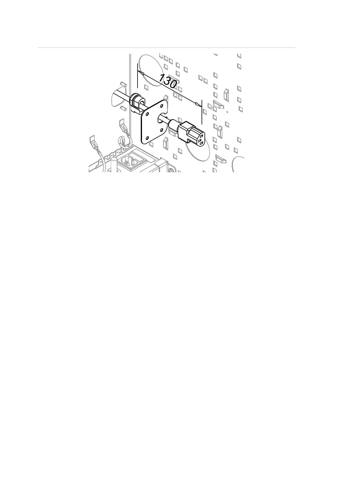
Figure 6: Power entry guard plate installed to block power entry cut-out
When the power cable is routed into the enclosure through the power entry
cutout the power entry guard plate provides strain relief to the cable.
1. Pass the cable through the cut-out.
2. Place the grommet around the cable approximately 130mm from its end.
3. Push the grommet, with cable, through the opening in the plate.
4. Place the power entry guard plate assembly over the studs inside the
enclosure and fasten in place with the nuts and washers provided.
5. Insert the end of the power cable into the transformer power inlet.
Installing the cable entry guard plate
See Figure 7 on page 9.
When 50 x 50 mm conduit is used the cable entry guard plate is not required
(Figure 5, item 1).
When 50 x 25 mm conduit is used the cable entry guard plate can be placed over
the studs either side of the cable entry cut-out, as shown in Figure 5, item 2, and
fastened using the nuts and washers provided.
When the cable entry cut-out is not required (item 3), it can be blocked by
inverting the cable entry guard plate. Place the tongue of the plate in the cut-out
while the holes go over the studs and fasten in place with the nuts and washers
provided.