Chapter 1: Installation
CDC4 Door Controller Installation and Programming Manual 31
Note: If output expansion boards are used, then a value for output controllers
must be programmed for CDC4 in Downloader, where 1 represents each eight
outputs or open collector outputs. See “Output modules number” on page 83 for
details.
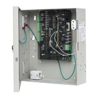
The PWR link (Figure 12 on page 13, item 14) enables CDC4 to power a
connected output expansion module. Remove the link if the output card is
powered from an external 12 V supply. Note: If two relay boards are used, link
should be removed and the relay boards should be powered from external
supply.
Note: Devices connected to the buses and powered by the door controller must
comply with “Output fusing and user current draw” on page 38.