Intermec EasyCoder 501 – Service Manual Ed. 7
12
Chapter 1 Models and Options
1.1 Identifi cation, cont.
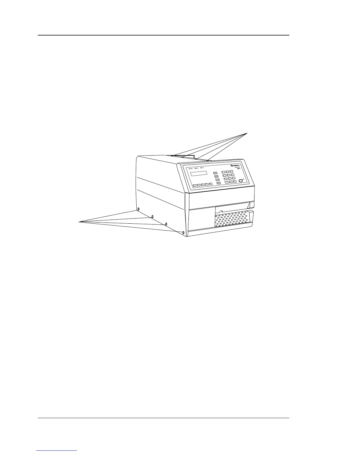
Finally, you may want to inspect the electronics compartment. To
do so, you will have to remove the left-hand cover plate.
For safety reasons, we recommend that you switch off the
printer and remove the power cord fi rst.
(All high-voltage wires are insulated, but could be damaged and
should therefore be inspected at service.)
Using a #T10 Torx screwdriver, remove the four screws at the
bottom of the cover plate and the four screws along the upper edge,
hidden under the right-hand cover.
In the electronics compartment you may check, for example:
• Type of CPU-Board fi tted?
• Fingerprint EPROM version?
• Confi guration EPROM type?
• Optional ROM-expansion EPROMs fi tted?
• Correct type of GAL circuits?
• Optional Real-Time Clock circuit (RTC) fi tted?
• Type of interface on "uart1:"?
• Optional interface board fi tted?
• Type of interface(s) on interface board?
Refer to the descriptions of the CPU-board and the various inter-
face boards in Chapters 17-23.
4 Screws (#T10)
4 Screws (#T10)