20
FRONT RIGGINGSPROCEDURE 1
6. Install the articulating footplate to one (1) of four (4)
mounting positions.
NOTE: If desired depth is not obtainable, rotate the
half clamp on the footplate support tube 180
o
.
7. Install and tighten the two (2) flat screws and lock-
nuts.
NOTE: The settings for positioning the articulating
footplates on the half-clamps may vary for each
footplate.
8. Adjust the articulating footplate angle if neces-
sary. Refer to ADJUSTING ARTICULATING
FOOTPLATE ANGLE in this section of the
manual.
ADJUSTING/INSTALLING THE SWING
UNDER/NON-SWING UNDER
FOOTBOARDS (FIGURE 3)
WARNING
When determining the angle, depth or height of the
swing under/non-swing under footboards when the
wheelchair is in the standard position, make sure
the back of the swing under/non-swing under
footboards DOES NOT interfere with the movement
of casters.
NOTE: The swing under/non-swing under
footboards can mount onto the standard or re-
versed positions of the wheelchair.
Adjusting
FOOTBOARD ANGLE.
1. Loosen, but do not remove the two (2) hex screws
that secure the swing under/non-swing under
footboard to the support assemblies.
2. Adjust the swing under/non-swing under footboard
to the desired angle for the user.
3. Securely tighten the swing under/non-swing under
footboard to the support assemblies with the two (2)
hex screws.
FOOTBOARD DEPTH.
1. Remove the four (4) flat screws and locknuts that
secure the swing under/non-swing under footboard
to the footboard clamps.
2. Position the swing under/non-swing under footboard
to one (1) of four (4) positions to accommodate the
user.
3. Reinstall the four (4) flat screws and securely tighten
the with four (4) locknuts.
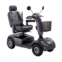
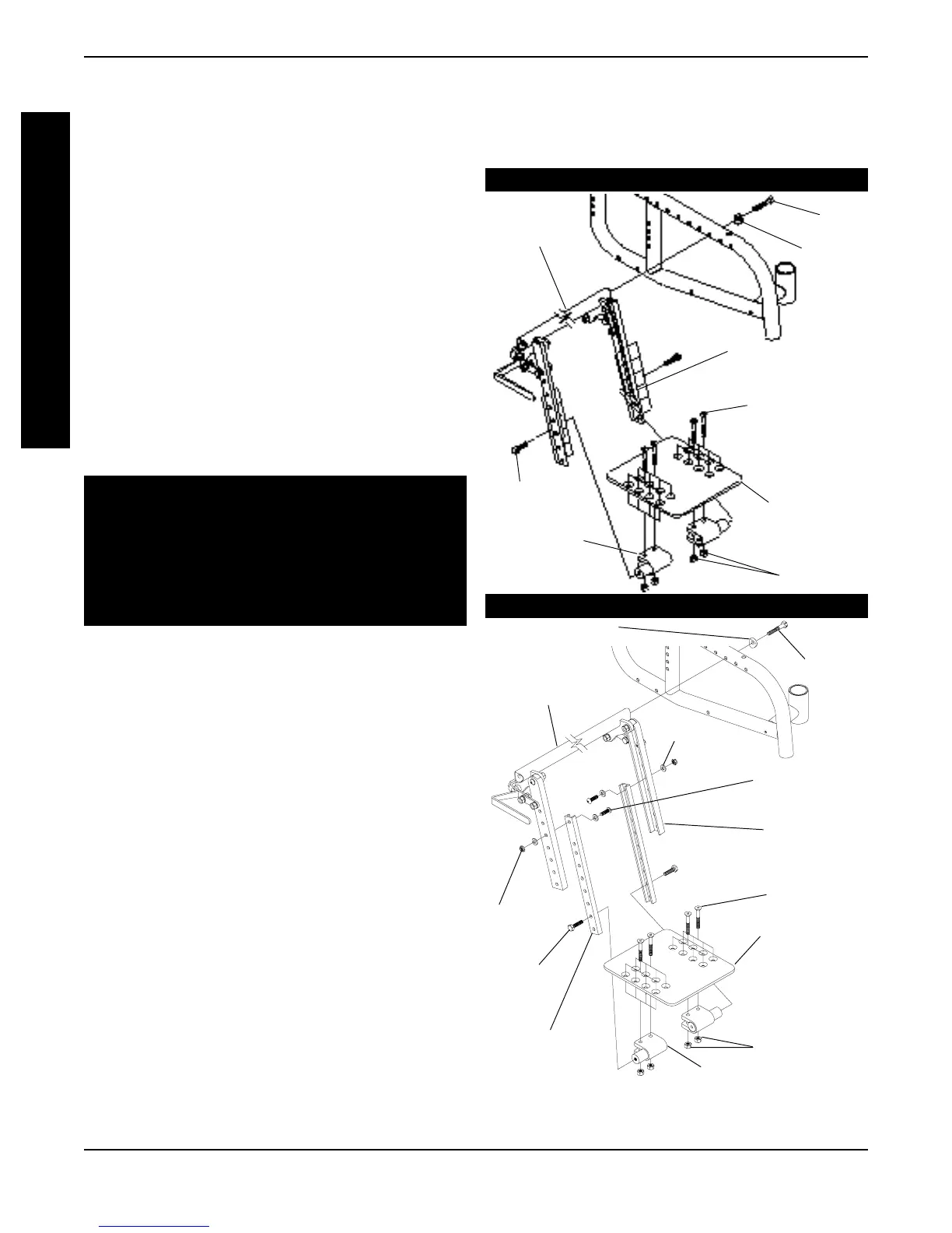
FIGURE 3 - ADJUSTING/INSTALLING THE
SWING UNDER/NON-SWING UNDER
FOOTBOARDS
Crossmember
Locknuts
Swing Under
Footboard
Flat
Screws
Support
Assemblies
Socket
Screws
Footboard Clamps
Hex
Screws
Locknuts
Washer
Channels
Coved Spacer
Hex Screw
F
R
O
N
T
R
I
G
G
I
N
G
S
NOTE: Installations shown for standard postion/
swing under footboard only for clarity. Installa-
tion procedure is the same for Reversed/Non-
Swing under footboards.
LONG FRAME
Swing Under
Footboard
Hex
Screw
Locknuts
Flat Screws
Cross
member
Support
Assemblies
Hex
Screws
Coved
Washer
Footboard
Clamps
SHORT FRAME