52
This Procedure includes the following:
Adjusting the Wheel Locks
Installing Wheel Lock Handle to Link (Reverse
Position ONLY) (Optional)
Installing/Adjusting the Anti-tippers
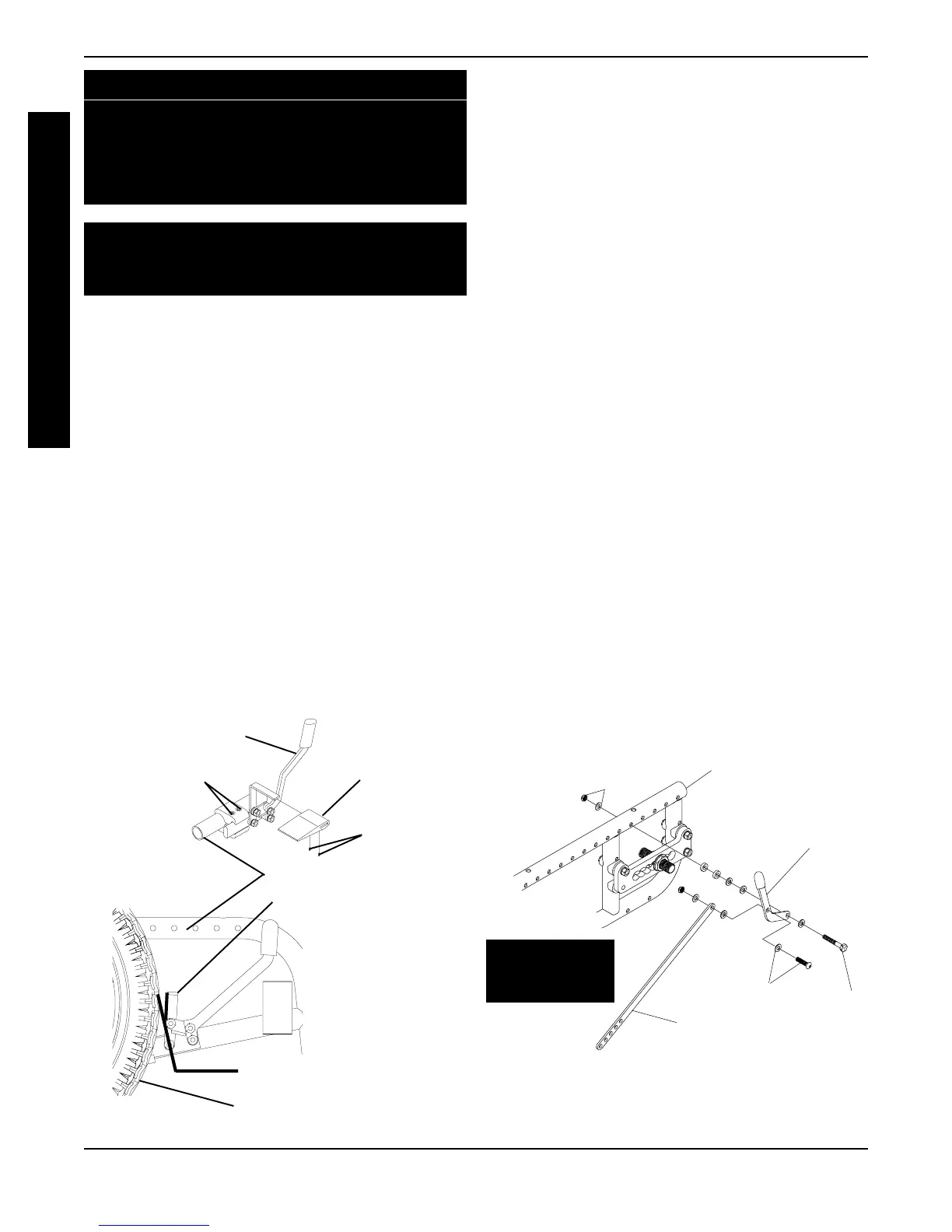
4. Measure the distance between the WHEEL LOCK
SHOE and the LARGE WHEEL.
5. Slide the wheel lock along the wheelchair until the
measurement is between 5/32 and 5/16-inches.
6. Tighten the wheel lock to the wheelchair frame.
7. Repeat this procedure for the opposite wheel lock.
8. Engage the wheel locks and push against the wheel-
chair to determine if the wheel locks engage the large
wheels enough to hold the wheelchair.
9. Repeat STEPS 1-8 until the wheel locks engage the
large wheels enough to hold the wheelchair.
INSTALLING WHEEL LOCK HANDLE TO LINK
(REVERSE POSITION ONLY) (OPTIONAL)
(FIGURES 2 AND 3)
1. Determine large wheel size, either 16, 20, 22 or 24-
inch.
2. Determine axle mounting position (Axle Mounting
Plate), either 1st, 2nd or 3rd hole from FRONT of
wheelchair (FIGURE 3).
3. Refer to FIGURE 3 and select correct link mounting
hole.
4. Assemble the wheel lock handle to link using the
button screw, washers and locknut provided
(FIGURE 2).
5. Using the NEW hardware provided, secure the wheel
lock handle w/link to the 5th or 6th frame mounting
hole (FIGURE 2).
FIGURE 1 - ADJUSTING THE WHEEL LOCKS
WARNING
After adjustments and before use make sure all
attaching hardware is securely tightened.
ADJUSTING THE WHEEL LOCKS (FIGURE 1)
NOTE: Before adjusting the wheel locks, make
sure the tires are inflated to the recommended
psi on the sidewall of the tire.
NOTE: If the wheelchair is equipped with the
swing under footboard and the large wheels are
in the most rearward position, the wheel lock
shoe spacers included with the wheelchair must
be used to ensure the wheel locks engage the
large wheels.
1. If necessary, secure wheel lock shoe spacer
on wheel lock, as shown in FIGURE 1, with set
screws provided.
2. Loosen the socket screws that secure the wheel
locks to the wheelchair frame.
3. Make sure the wheel lock is disengaged from
the large wheels.
PROCEDURE 7 WHEEL LOCKS/ANTI-TIPPERS
FIGURE 2 - INSTALLING WHEEL LOCK HANDLE
TO LINK (REVERSE POSITION ONLY)
(OPTIONAL)
REVERSED
POSITION
ONLY
Link
Step 4
Front of Wheelchair in
Reverse Position
Step 6
Wheel Lock
Handle
Step 5
W
H
E
E
L
L
O
C
K
S
Wheel Lock Shoe
Wheelchair Frame
Set Screws
5/32 to 5/16-inch Gap
Large Wheel
Wheel Lock Handle
Socket Screws
Wheel Lock
Shoe Spacer